Technology Solutions
Instruction Manual
Tek-Flux 1400A
www.tek-trol.com
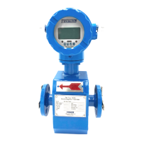
• Flow meter installation in a measuring well:
4 Electrical Installations
4.1 Safety Instruction
• Please cut off power supply before connecting the device
• Check the cable model before connecting the cable
• Follow procedure for cable into lead collar: at first, loosen the gland nut on lead collar
and take off blind; secondly, put gland nut and rubber ring on cable, make the cable
through lead collar; finally, straighten out cable, screw gland nut tight to make rubber
ring press cable.
• When wire stripping, do not damage insulating layer which should be reserved.
4.2 Grounding
Grounding of Tek-Flux 1400A is very important. Bad grounding will result in abnormal
operation. Flow meter sensor part should have separate grounding cable (whose
sectional area of copper core should be 1.6mm
2
, ground resistance should be less than
10Ω.).
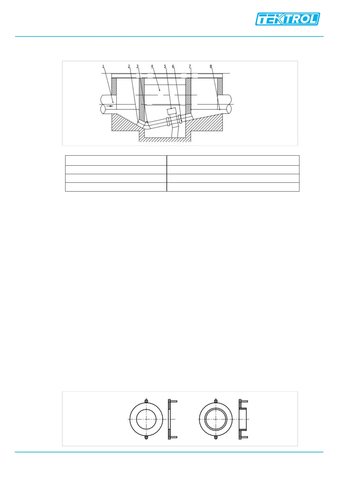
4.2.1 Grounding Ring
If the pipeline connected with sensor is insulative, grounding ring will be needed, the
material should be same as electrode material. If the medium is abrasive, then
grounding ring with neck should be selected.
 Loading...