Technology Solutions
Instruction Manual
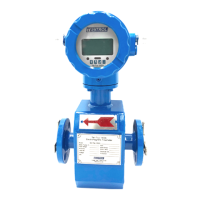
Tek-Flux 1400A
www.tek-trol.com
Table of Contents
1 Safety Instructions .................................................................................................... 3
1.1 Intended Use ............................................................................................................... 3
1.2 Safety Instructions from the Manufacturer ................................................................... 3
1.2.1 Disclaimer .......................................................................................................................... 3
1.2.2 Product Liability and Warranty ......................................................................................... 3
1.2.3 Information Concerning the Documentation .................................................................... 3
1.3 Safety Precautions ....................................................................................................... 3
1.4 Packaging, Transportation and Storage ......................................................................... 4
1.4.1 Packaging ........................................................................................................................... 4
1.4.2 Transportation................................................................................................................... 5
1.4.3 Storage .............................................................................................................................. 5
1.4.4 Nameplate ......................................................................................................................... 6
2 Product Description .................................................................................................. 7
2.1 Introduction ................................................................................................................ 7
2.2 Measuring Principle ..................................................................................................... 7
2.3 Specifications ............................................................................................................... 8
2.3.1 Technical ........................................................................................................................... 8
2.3.2 Electrode Material Selection ............................................................................................. 9
2.3.3 Lining Material .................................................................................................................. 9
2.3.4
Flow Range and Nominal Diameter Selection ................................................................... 9
2.4 Dimensional Drawings ............................................................................................... 10
2.5 Model Chart............................................................................................................... 11
3 Installation.............................................................................................................. 12
3.1 Correct Mounting Point .............................................................................................. 12
3.2 Requirements for Measuring Flow Meter Accuracy ..................................................... 13
3.3 Installation Condition ................................................................................................. 13
4 Electrical Installations ............................................................................................. 15
4.1 Safety Instruction....................................................................................................... 15
4.2 Grounding ................................................................................................................. 15
4.2.1 Grounding Ring ................................................................................................................ 15
4.2.2 Grounding Mode ............................................................................................................. 16
4.3 Transmitter Connections ............................................................................................ 16
4.3.1 Basic Circuit of the Transmitter ....................................................................................... 16
4.3.2 Power Supply Wiring ....................................................................................................... 17
4.4 Connection of Cable ................................................................................................... 19
4.4.1 Output and Power Cable ................................................................................................. 19
4.5 Digital Output ............................................................................................................ 20
4.5.1 Frequency Output ........................................................................................................... 20
4.5.2 Pulse Output Mode .........................................................................................................
21
4.5.3 The Connection of Digital Output ................................................................................... 21
4.5.4 Digital Output Connection as Photoelectric Coupling (PLC etc.) .................................... 21
4.5.5 Digital Output Connection as Relay ................................................................................ 22
4.6 Simulation Signal Output and Calculation ................................................................... 22
4.6.1 Simulation Signal Output ................................................................................................ 22
4.6.2 Simulation Signal Output Adjust ..................................................................................... 22
4.6.3 Transmitter Connection of Current Output .................................................................... 23
5 Operation ............................................................................................................... 24
5.1 Key and Display ......................................................................................................... 24
5.2 Parameter Setting ...................................................................................................... 24
 Loading...