8. Follow instructions to install the firmware.
NOTE. Do not power off the oscilloscope or remove the USB flash drive until the oscilloscope finishes installing the
firmware. The oscilloscope displays a message when it is OK to turn off the oscilloscope.
9. When the firmware install is finished, remove the USB drive and restart the oscilloscope.
To confirm the firmware installation:
1. Tap Help > About in the Menu bar.
2. Verify that the firmware version number listed on the screen is the same version that you downloaded.
Run Signal Path Compensation (SPC)
Run SPC at regular intervals for best measurement accuracy. You should run SPC whenever the ambient (room) temperature
has changed by more than 5 °C (41 °F), or once a week if you use vertical scale settings of 5 mV per division or less.
Signal Path Compensation (SPC) corrects for DC level inaccuracies in the internal signal path, caused by temperature variations
and/or long-term signal path drift. Failure to run SPC on a regular basis may result in the oscilloscope not meeting warranted
performance levels at low volts per division settings.
Prerequisite: Disconnect all probes and cables from the front-panel channel inputs and rear-panel signal connectors.
1. Power on and warm up the oscilloscope for at least 20 minutes.
2. Tap Utility > Calibration.
3. Tap Run SPC. The SPC Status readout shows Running while SPC is running. SPC can take several minutes per channel
to run, so wait until the SPC Status message changes to Pass before reconnecting probes and using the oscilloscope.
CAUTION. You can abort the SPC calibration by tapping Abort SPC. This may leave some channels uncompensated,
resulting in possible inaccurate measurements. If you do abort the SPC, make sure to run the SPC procedure completely
before using the instrument to take measurements.
4. Close the Calibration configuration dialog when SPC has completed.
5. If the SPC fails, write down any error message text. Make sure that all probes and cables are disconnected and run the SPC
again. If the SPC still fails, contact Tektronix Customer Support.
Compensate the TPP0500B or TPP1000 probes
Probe compensation adjusts the high frequency response of a probe for best waveform capture and measurement accuracy. The
oscilloscope can automatically test and store compensation values for an unlimited number of probe/channel combinations.
The oscilloscope stores the compensation values for each probe/channel combination, and automatically recalls the
compensation values when you plug in the probe. Probe compensation status is shown in the Probe Setup panel of the Channel
configuration menu.
■
If the Probe Compensation Status field displays Pass, the probe is compensated and ready for use.
■
If the Probe Compensation Status field displays Default, the attached probe has not been compensated and needs to have
this probe compensation procedure run.
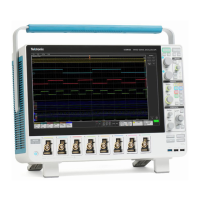
Configure the instrument
30 MSO54, MSO56, MSO58 Installation and Safety Manual

 Loading...