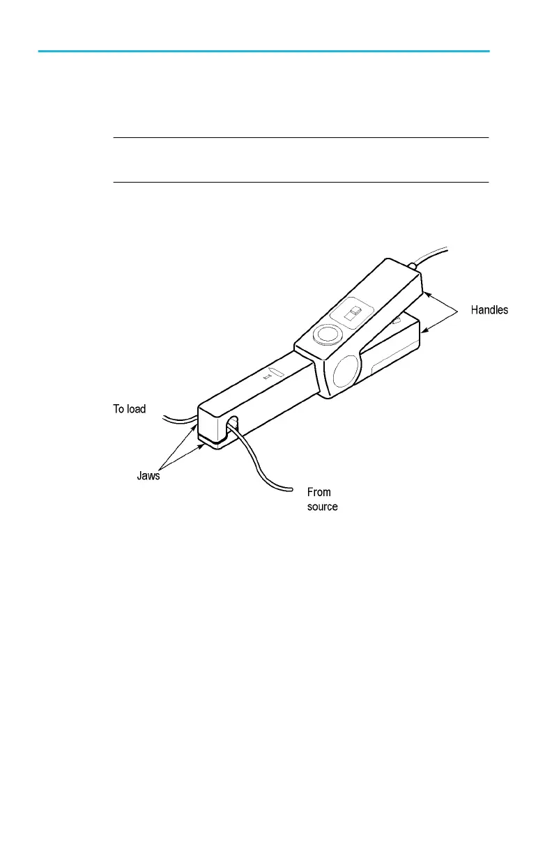
4. Connect the probe to the circuit by opening the jaws and clamping
around the conductor. See Figure 2: Connecting the A622 current
probe on page 4.
NOTE. Clamping around both the "hot" and neutral wires may give
you a zero reading.
(Remember to unclamp the probe from the conductor before
disconnecting it from your meter or instrument.)
Figure 2: Connecting the A622 current probe
5. Adjust the probe and channel as necessary to get a clear view of
the signal. Set the channel to DC volts to see both the AC and DC
currents; set the channel to AC to see the AC current only.
The current drawn by some devices looks much different than that of
others. While the RMS current may be low, the momentary peaks can
be quite high. The following figures shows the difference between the
line current drawn by a resistive load and a motor controller.
Operating Basics
4 A622 Instructions