Operstlng
Instructions-AA
501
10
Hz
20 30 50 100
Hz
200 300 500
1
kHz 2
5
10 kHz 20 30 50 100 kHz
2958-08A
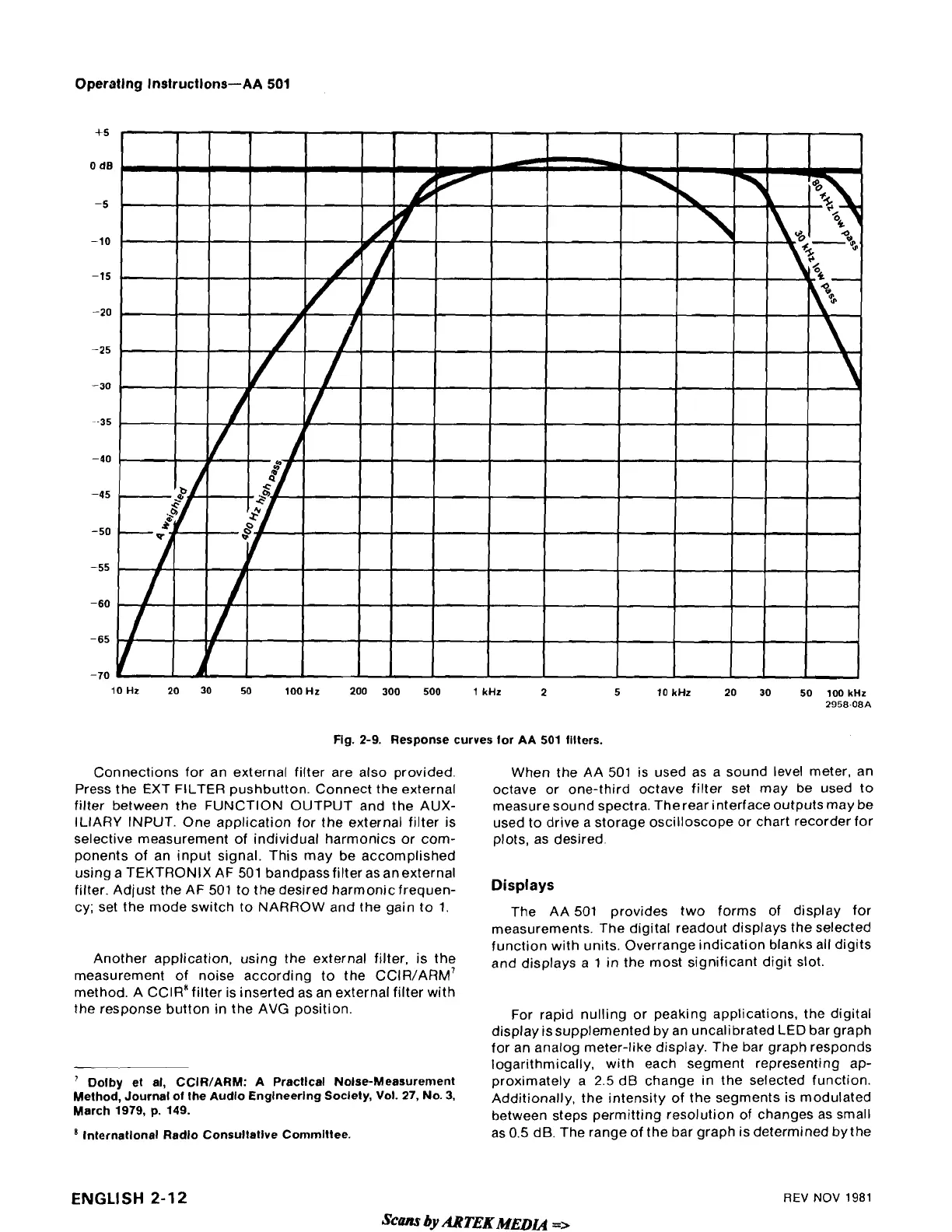
Flg. 2-9. Response curves for AA
501
filters.
Connections for an external filter are also provided.
Press the EXT FILTER pushbutton. Connect the external
filter between the FUNCTION OUTPUT and the AUX-
ILIARY INPUT. One application for the external filter is
selective measurement of individual harmonics or com-
ponents of an input signal. This may be accomplished
using a TEKTRONIX AF 501
bandpass filter as an external
filter. Adjust the AF 501 to the desired
harmonicfrequen-
cy; set the mode switch to NARROW and the gain to
1.
Another application, using the external filter, is the
measurement of noise according to the
CCIR/ARM~
method.
A
C~1R"ilter is inserted as an external filter with
the response button in the AVG position.
Dolby et al, CCIR/ARM: A Practical Nolse-Measurement
Method, Journal of the
Audio Englneerlng Soclety,
Vol.
27,
No.
3,
March 1979, p. 149.
lnternatlonal Radio
Consultative
Committee.
When the AA 501 is used as a sound level meter, an
octave or one-third octave filter set may be used to
measure sound spectra.
Therear interface outputs may be
used to drive a storage oscilloscope or chart recorder for
plots, as desired.
Displays
The AA 501 provides two forms of display for
measurements. The digital readout displays the selected
function with units. Overrange indication blanks all digits
and displays a 1 in the most significant digit slot.
For rapid nulling or peaking applications, the digital
display is supplemented by an uncalibrated LED bar graph
for an analog meter-like display. The bar graph responds
logarithmically, with each segment representing ap-
proximately a
2.5
dB change in the selected function.
Additionally, the intensity of the segments is modulated
between steps permitting resolution of changes as small
as 0.5 dB. The range of the bar graph is determined
by
the
ENGLISH
2-12
REV
NOV
1981
Scans
by
ARTEK
MEDL4
=>