Operatlng
Instructions-AA
501
SG
505
Oscillator
AA501
Dlstortlon Analyzer Oscilloscope
Shielded twlsted pair
2958-02
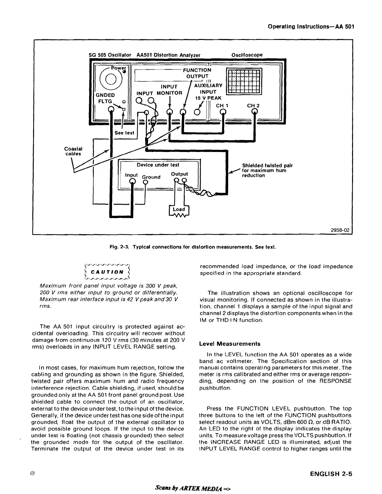
Fig.
2-3.
Typlcal connectlons for distortlon measurements. See text.
Maximum front panel input voltage is
300
V
peak,
200
V
rrns either input to ground or differentially.
Maximum rear interface input is
42
V
peak and
30
V
rms.
The
AA
501 input circuitry is protected against ac-
cidental overloading. This circuitry will recover without
damage from continuous 120 V rms (30 minutes at 200 V
rms) overloads in any INPUT LEVEL RANGE setting.
In most cases, for maximum hum rejection, follow the
cabling and grounding as shown in the figure. Shielded,
twisted pair offers maximum hum and radio frequency
interference rejection. Cable shielding, if used, should be
grounded only at the AA 501 front panel ground post. Use
shielded cable to connect the output of an oscillator,
external to the device under test, to the input of the device.
Generally, if the device under test has one side of the input
grounded, float the output of the external oscillator to
avoid possible ground loops. If the input to the device
under test is floating (not chassis grounded) then select
the grounded mode for the output of the oscillator.
Terminate the output of the device under test in its
recommended load impedance, or the load impedance
specified in the appropriate standard.
The illustration shows an optional oscilloscope for
visual monitoring. If connected as shown in the illustra-
tion. channel 1 displays a sample of the input signal and
channel 2 displays the distortion components when in the
IM or THD+N function.
Level Measurements
In the LEVEL function the AA 501 operates as a wide
band ac voltmeter. The Specification section of this
manual contains operating parameters for this meter. The
meter is rms calibrated and either rrns or average respon-
ding, depending on the position of the RESPONSE
pushbutton.
Press the FUNCTION LEVEL pushbutton. The top
three buttons to the left of the FUNCTION pushbuttons
select readout units as VOLTS,
dBm
600
n,
or dB RATIO.
An LED to the right of the display indicates the display
units. To measurevoltage press the VOLTS pushbutton. If
the INCREASE RANGE LED is illuminated, adjust the
INPUT LEVEL RANGE control to higher ranges until the
ENGLISH
2-5