Section
2-AA
501
OPERATING INSTRUCTIONS
Preparation For Use
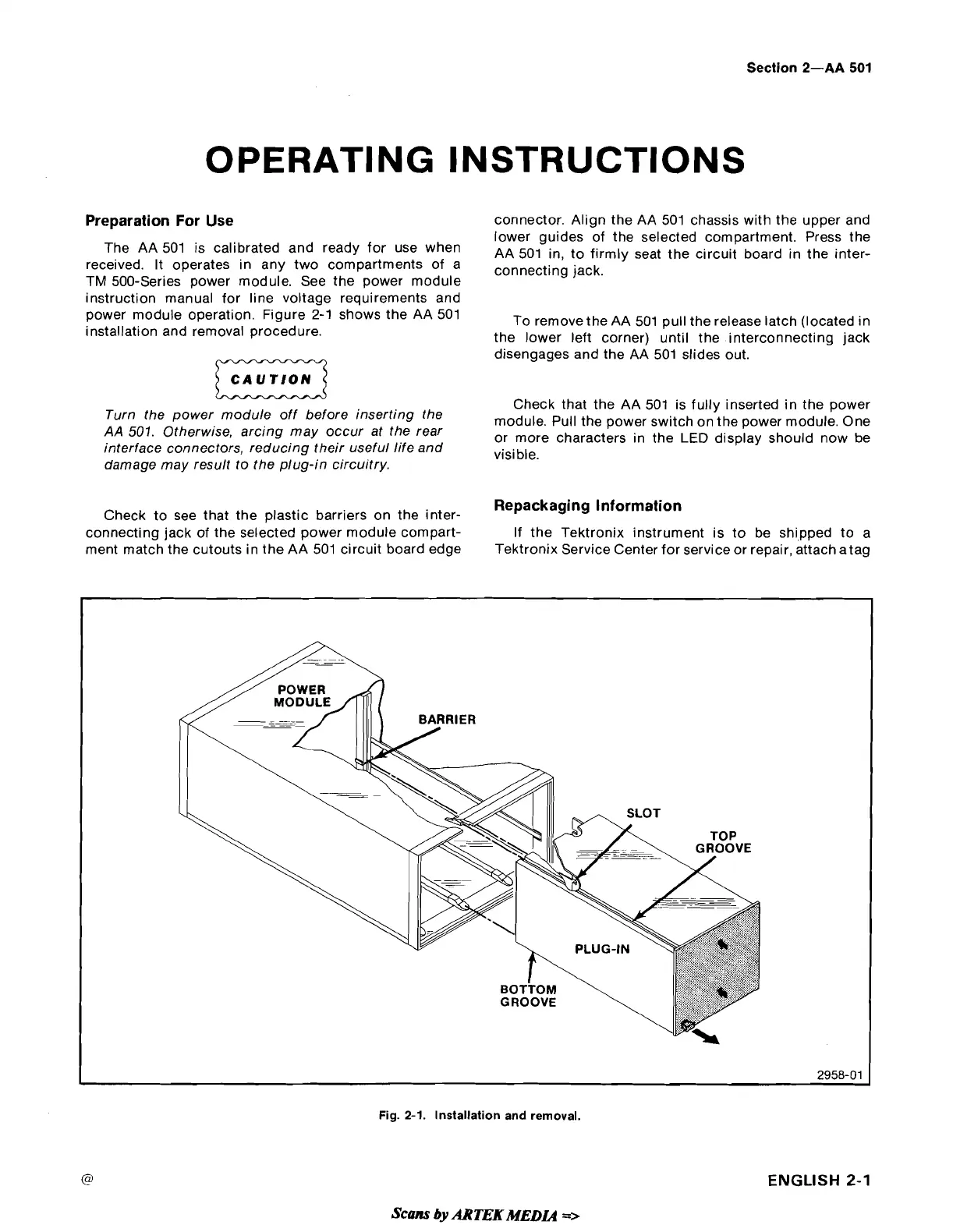
connector. Align the AA 501 chassis with the upper and
lower guides of the selected compartment. Press the
The AA is calibrated and
use
when
AA 501 in, to firmly seat the circuit board in the inter-
received. It operates in any two compartments of a
connecting
jack.
TM 500-Series power module. See the power module
instruction manual for line voltage requirements and
power module operation. Figure
2-1
shows the AA 501
To remove the AA 501 pull the release latch (located in
installation and removal procedure.
the lower left corner) until the interconnecting jack
disengages and the AA 501 slides out.
Check that the AA 501 is fully inserted in the power
Turn the power module off before inserting the
module. Pull the power switch on the power module. One
AA
501.
Otherwise, arcing may occur at the rear
or more characters in the
LED
display should now be
interface connectors, reducing their useful life and
visible.
damage may result to the plug-in circuitry.
Check to see that the plastic barriers on the
inter-
Repackaging Information
connecting jack of the selected power module compart-
If the Tektronix instrument is to be shipped to a
ment match the cutouts in the AA 501 circuit board edge
Tektronix Service Center for service or repair, attach atag
Fig.
2-1.
Installation and removal.
ENGLISH
2-1
Scans
by
AR
TEK
MEDL4
=>