Cali bration-AA
501
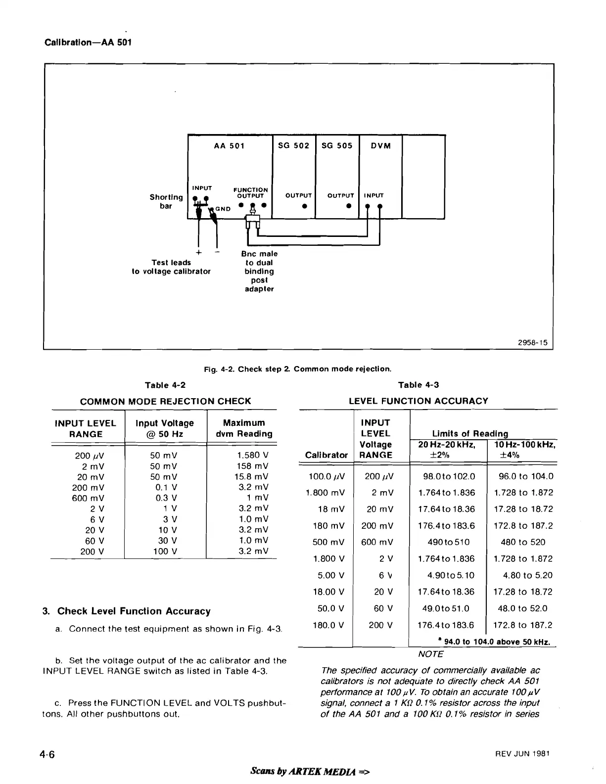
Fig. 4-2. Check step 2. Common mode rejection.
AA
501
INPUT
FUNCTION
Shorting
OUTPUT
bar
Table
4-2
Table
4-3
COMMON MODE REJECTION CHECK
LEVEL FUNCTION ACCURACY
+
-
Bnc male
Test leads to dual
voltage calibrator binding
post
adapter
DVM
INPUT
)a
SG 502
OUTPUT
3.
Check Level Function Accuracy
SG 505
OUTPUT
•
INPUT LEVEL
RANGE
200 pV
2 rnV
20 rnV
200 rnV
600 rnV
2
V
6
V
20 V
60 V
200 V
a. Connect the test equipment as shown in Fig.
4-3.
1
INPUT
1
Input Voltage
@
50 Hz
50 mV
50 mV
50 rnV
0.1 V
0.3 V
1
V
3 V
10 V
30 V
100 V
LEVEL Limits of Reading
20 Hz-20 kHz,
1
10 Hz-100 kHz,
Maximum
dvm Reading
1.580 V
158
mV
15.8 rnV
3.2 rnV
1
rnV
3.2 rnV
1.0 rnV
3.2 mV
1.0 rnV
3.2 rnV
Calibrator
I
RANGE
1
f
2%
I
f4%
I
1
94.0 to 104.0 above 50
kHz.
NOTE
b. Set the voltage output of the ac calibrator and the
INPUT
LEVEL RANGE
switch as listed in Table
4-3.
The specified accuracy of commercially available ac
calibrators is not adequate to directly check
AA
501
performance at 100
p
V.
To obtain an accurate 100
p
V
c. Press the FUNCTION
LEVEL
and
VOLTS
pushbut-
signal, connect a
1
KSZ
0.1
%
resistor across the input
tons.
All
other pushbuttons out.
of the
AA
501 and a 100
Kf2
0.1% resistor in series
4-6
REV
JUN
1981
Scans
by
ARTEK
MEDLQ
=>