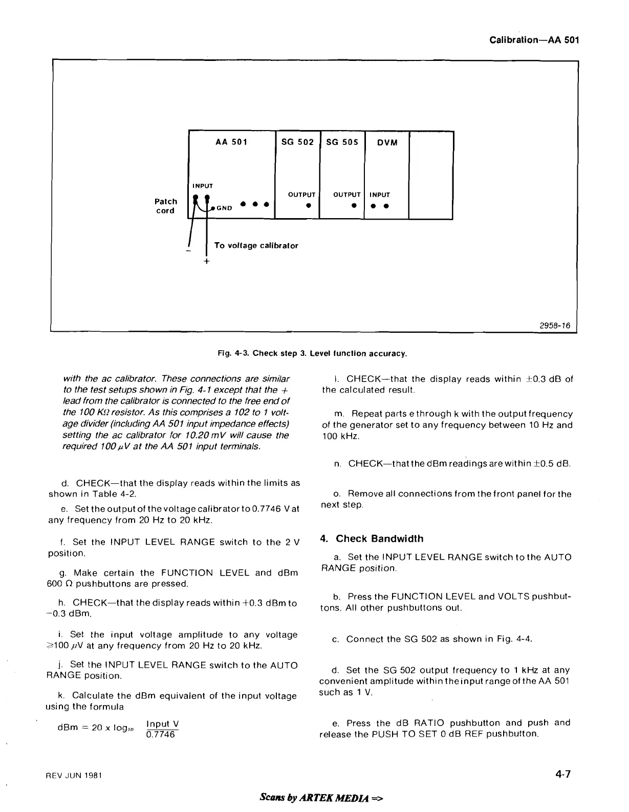
Fig.
4-3.
Check
step
3.
Level function accuracy.
AA
501
INPUT
Patch
cord
with the ac calibrator. These connections are similar
I. CHECK-that the display reads within
f0.3
dB of
to the test setups shown in Fig.
4-
1 except that the
+
the calculated result.
lead from the calibrator is connected to the free end of
the 100
Kf2
resistor. As this comprises a 102 to 1 volt-
m. Repeat parts e through k with the output frequency
age divider (including AA 501 input impedance effects)
of the generator set to any frequency between
10
Hz and
setting the ac calibrator for 10.20 mV will cause the
100
kHz.
required 100
p
V at the AA 50 1 input terminals.
n. CHECK-that the dBm readings arewithin
k0.5
dB
-
To voltage calibrator
+
SG 502
OUTPUT
.
d. CHECK-that the display reads within the limits as
shown
in
Table
4-2.
o. Remove all connections from the front panel for the
e. Set the output of the voltage calibrator to
0.7746
Vat
next
step.
any frequency from
20
Hz to
20
kHz.
f.
Set the INPUT LEVEL RANGE switch to the
2
V
4-
Check
Bandwidth
position.
a. Set the INPUT LEVEL RANGE switch to the AUTO
g. Make certain the
FUNC'TION LEVEL and dBm
RANGE position.
600
R
pushbuttons are pressed.
SG 505
OUTPUT
.
b. Press the FUNCTION LEVEL and VOLTS pushbut-
h. CHECK-that the display reads within
+0.3
dBm to
tons,
All
other
pushbuttons
out,
--0.3
dBm.
DVM
INPUT
0.
i. Set the input voltage amplitude to any voltage
c. Connect the SG
502
as shown in Fig.
4-4.
3100
pV at any frequency from
20
Hz to
20
kHz.
j.
Set the INPUT LEVEL RANGE switch to the AUTO
RANGE position.
d. Set the SG
502
output frequency to
1
kHz at any
convenient amplitude within
theinput range of the AA
501
k. Calculate the dBm equivalent of the input voltage
Such
V.
using the formula
Input
V
dBm
=
20
x
logrn
-
0.7746
e. Press the dB RATIO pushbutton and push and
release the PUSH TO SET
0
dB
REF
pushbutton.
REV
JUN
1981
4-7
Scans
by
ARTEK
MEDL4
=>