Removal and Installation Procedures
6-8 AFG3000 Series Arbitrary/Function Generators Service Manual
Summary of Procedures
Disassembly for replacement is best achieved by removing and replacing the
modules in a specific order. Complete disassembly is best achieved by following
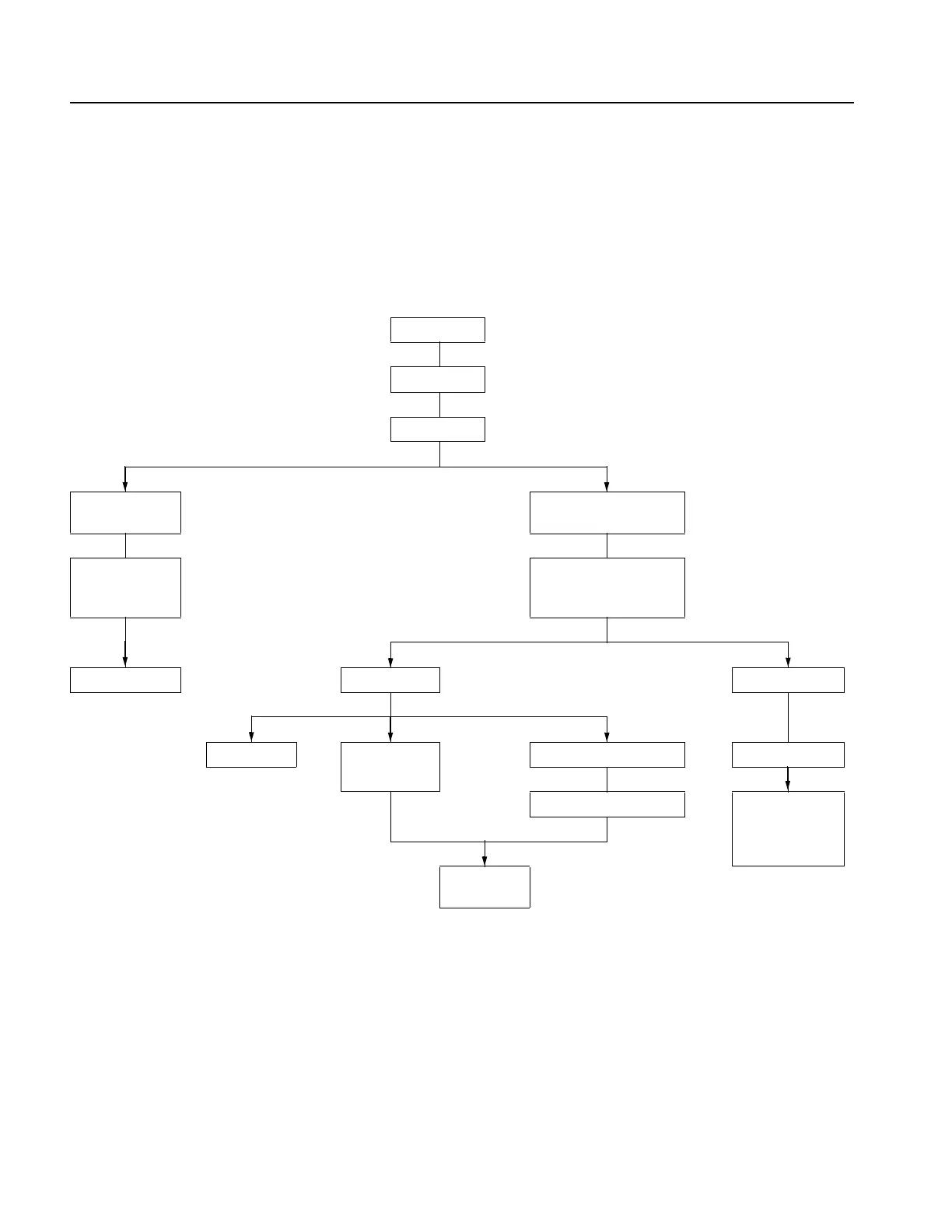
the procedures in the order given in Figure 6-1.
Figure 6-1: Disassembly order
Tools Required
Use the following tools to remove and replace all modules:
Torque-limiting screwdriver, long shank, 8 lb-in (0.85 N m) range with Torx
T-15 tip
Flip feet
Rear case
Top cover
Front case
and Keypad
Output board (AFG310x,
AFG325x)
A75 Front-panel
board
Separation of Rear
module and Main
chassis
Display module Rear module Main chassis
Inverter
A82 BNC
Insulator board
Fan Generator board
Power supply
A81 BNC
Insulator board,
BNC bracket
A72 CPU
board

 Loading...


