Brief procedures
Checking the a
nalog
channel outputs
Required equ ipment Prerequisites
Oscilloscope
One TCA-SMA adapter
One 50 Ω SMA cable
One 50 Ω SMA terminator
None
1. Set the test oscilloscope a s follows:
a. Vertical scale: 200 mV/div (CH 1 and CH 2)
b. Horizontal scale: 100 ns/div
c. Input coupling: DC (CH 1 and CH 2)
d. Input impedance: 50 Ω (CH 1 and CH 2)
e. Position: +2 div (CH 1 and CH 2, if necessary)
f. Trigge
r source: CH 1
g. Trigger level: 0 mV
h. Trigger slope: Positive
i. Trigger mode: Auto
2. Press the AWG front panel All Outputs Off button (or click All Outputs Off
on the Home screen) to disable the outputs (front panel light on).
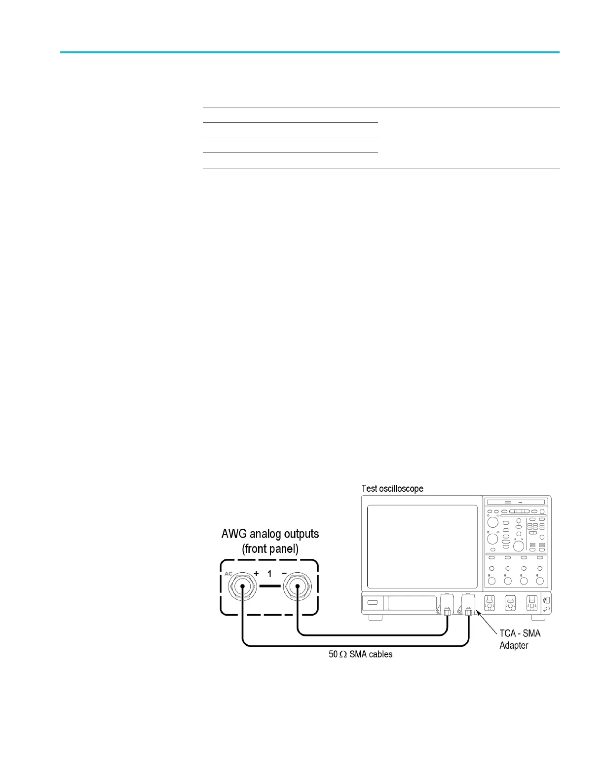
3. Connect CH 1 (+) of the AWG to channel 1 of the test oscilloscope using a
50 Ω SMA cable and a TCA-SMA adapter.
4. Connect CH 1 (–) of the AWG to channel 2 of the test o scilloscope using a
50 Ω SMA cable and a TCA-SMA adapter.
5. Click the Home tabonthedisplay.
AWG5200 Series Technical Reference 31
 Loading...


