Check input resistance ≥4 GHz models.
Equipment Required Prerequisites
One Digital Multimeter (Item 27)
One Dual-Banana Connector, (Item 5)
One precision 50 Ω coaxial cable (Item 4)
One SMA male-to-female BNC adapter (Item
19)
One SMA female-to-female adapter (Item 16)
One SMA male short circuit adapter (Item 25)
(See Prerequisites on page 116.)
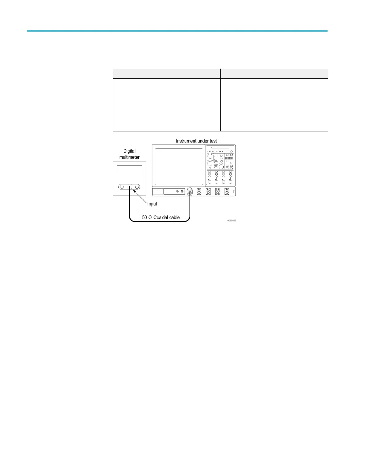
Figure 24: Input resistance test hookup, ≥4 GHz models
1. Install the test hookup and preset the instrument controls:
a. Initialize the instrument: Press the Default Setup button.
b. Short the cable from the multimeter by connecting a shorting adapter and
SMA-to-SMA adapter to the BNC-to-SMA adapter.
c. Read and record the resistance of the multimeter leads.
d. Hook up the test-signal source: Connect, through a 50 Ω precision
coaxial cable, the input of the multimeter to Ch 1 through adapters. (See
Figure 24: Input resistance test hookup, ≥4 GHz models on page 238.)
e. Set the Vertical Scale to 10 mV (6.25 mv for >20 GHz models) per
division
2. Check input impedance against limits:
a. Measure the impedance: Read and record the measured impedance.
b. Remove the dual banana connector from the digital multimeter (DMM),
turn it 180 degrees and reinsert it in the DMM input.
c. Measure the impedance: Read and record the measured impedance.
d. Add the two measurements and divide the result by 2.
e. Subtract the resistance of the multimeter leads from the average that you
calculated.
f. Enter the result on the test record.
Performance verification (MSO/DPO70000C, MSO/DPO70000DX, and DPO7000C series)
238 MSO70000C/DX, DPO70000C/DX, DPO7000C, MSO5000/B, DPO5000/B Series
 Loading...

