4. The Settings Bar contains System badges for setting Horizontal, T
rigger, Acquisition, and Date/Time parameters; Inactive Channel
buttons to turn on channels; Math/Ref/Bus button to add math, reference, and bus waveforms to the display; and Channel and
Waveform badges that let you configure the individual waveform parameters. Tap a channel or waveform button to add it to the screen
and display a badge. Double-tap a badge to open its configuration menu.
5. Configuration Menus let you quickly change the parameters of the selected user interface item. You can open configuration menus by
double-tapping on badges, screen objects, or screen areas.
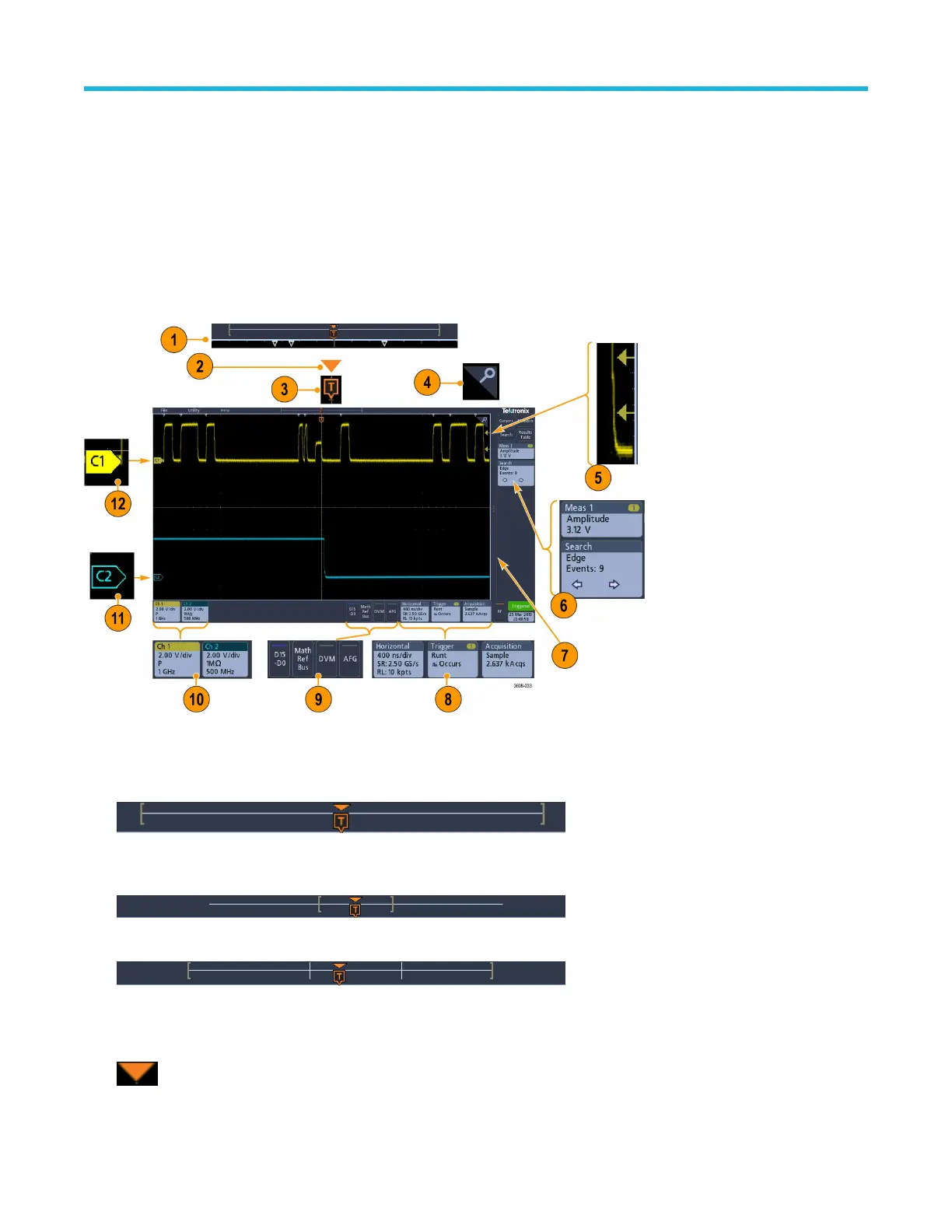
Identifying items in the time domain display
Each area of the user interface has a specific function that helps manage information or controls. This topic shows and describes the key
user interface elements.
1. The Waveform Record View is a graphical high-level view of the overall acquisition, how much of the acquisition is on the screen
(shown in brackets), the location of key time events including the trigger event, and the current position of waveforms cursors.
If you are changing the horizontal time scale while the oscilloscope acquisition is stopped, the brackets change position to show the
part of the waveform record that is being viewed relative to the current acquisition total record length.
If cursors are active on a waveform, the Waveform Record View shows the relative cursor positions as small vertical dashed lines.
When in Zoom mode, the Waveform Record View is replaced with the Zoom Overview. See Zoom user interface on page
31.
2. The Expansion Point icon on the waveform view shows the center point around which the waveform expands and compresses when
changing horizontal settings.
3. The T
rigger Position Indicator shows where the trigger event occurred in the waveform record.
Getting acquainted with your instrument
3 Series Mixed Domain Oscilloscope MDO32 and MDO34 Quick Start Manual 21
 Loading...


