Performance Verification
17. Push the OK Add M
easurement side-bezel button.
18. View the mean measurement value in the display and enter that mean value
as the test result in the test record.
19. Repeat steps 7 through 18 for each volts/division value listed in the results
table.
20. Push the front-panel channel button, change the oscilloscope bandwidth (for
example, 20 MHz, 250 MHz, or Full), and repeat steps 5 through 19.
21. Change the oscilloscope impedance to 1 MΩ and repeat steps 5 through 20.
22. Repeat steps 3 through 20 for each channel combination listed in the test
record and relevant to your model of oscilloscope (for example, 1, 2, 3, or 4).
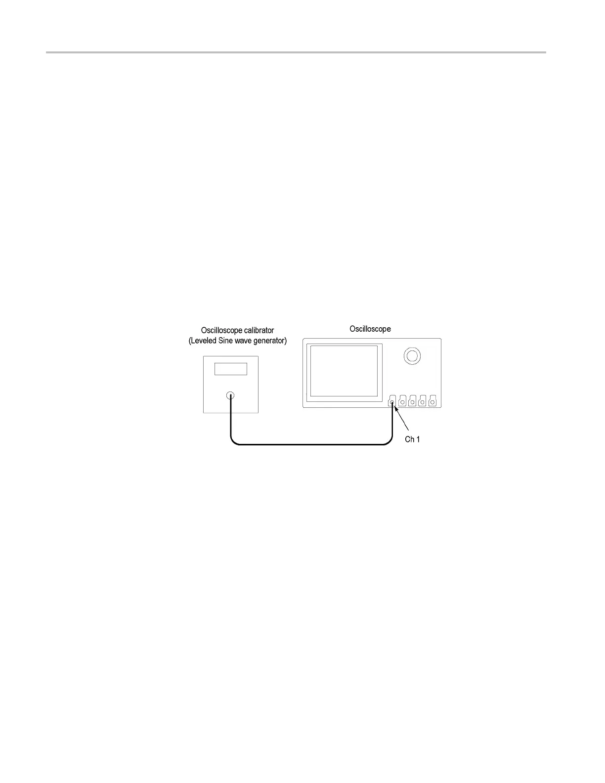
Check Bandwidth
This test checks the bandwidth at 50 Ω and 1 M Ω for each channel.
1. Connect the output of the leveled sine wave generator (for example, Wavetek
9500) to the oscilloscope channel 1 input as shown below.
2. Push the front-panel Default Setup button to set the instrument to the factory
default settings.
3. Push the channel button (1,2,3,4) for the channel that you want to check.
4. Set the calibrator to 50 Ω output impedance (50 Ω source impedance) and to
generate a sine wave.
5. Set the oscilloscope impedance to 50 Ω. Push the Impedance lower-bezel
button to select 50 Ω.
6. Turn the Vertical Scale knob to set the vertical scale, as shown in the test
record (for example, 1 mV/div, 2 mV/div, 5 mV/div).
7. Push the front-panel Acquire button.
8. Confirm that
the mode is set to Sample. If not push the Mode lower-bezel
button, and then push the Sample side bezel button.
9. Adjust the signal source to at least 8 vertical divisions at the selected vertic al
scale with a set frequency of 50 kHz. For example, at 5 mV/div, use a
38 MSO4000 and DPO4000 Series Specifications and Performance Verification
 Loading...


