Getting Started
P5205 Instruction Manual
3
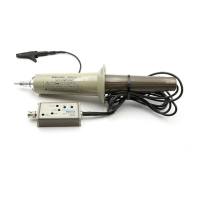
The P5205 has several features and accessories that make probing
and measurement a simpler task. Take a moment to familiarize
yourself with these items and their uses.
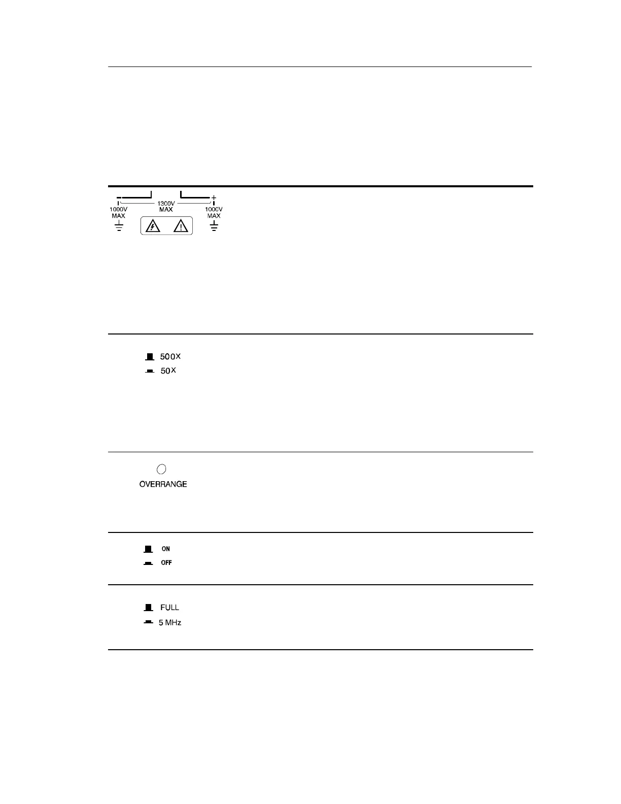
Differential Inputs. The inputs are rated to safely accept
a maximum of 1,000 V
RMS
CAT II between either
input and earth ground and a maximum difference of
1,300 V (DC + peak AC) between the inputs.
NOTE. The input safety ratings are valid for both
attenuation range setti ngs. However, for useful
measurements, the input should be kept to the
operating limits of the selected attenuation range of
130 V up to 1,300 V (DC + peak AC).
Attenuation Range. In the raised position the range
button sets the attenuation to 500X. In the lowered
position the range button sets the attenuation to 50X.
Use the 500X position for measurements up to a
maximum of 1,300 V (DC + peak AC) differential. Use
the 50X position for better signal resolution on
connections below 130 V (DC + peak AC).
Overrange Indicator. The overrange indicator lights red
if the voltage of the input signal exceeds the linear
operating range of the probe. When this happens, the
signal on the probe output does not accurately represent
the signal on the probe input.
Audible Overrange. In the raised position the overrange
button sets the audible alarm to sound whenever the
overrange indicator lights.
Bandwidth Select. In the raised position the bandwidth
button sets the full bandwidth (100 MHz minimum). In
the lowered position the bandwidth is restricted to
approximately 5 MHz.