Getting Started
4
P5205 Instruction Manual
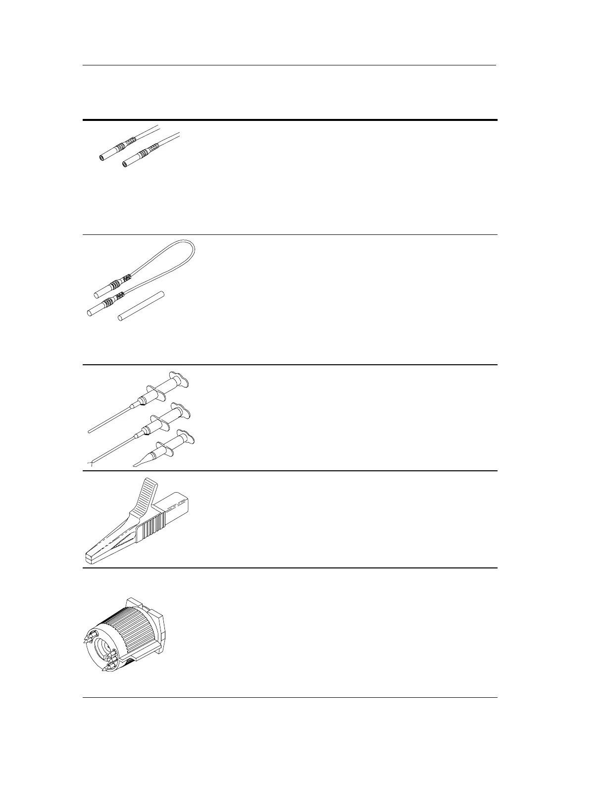
Input Leads. The input leads of the differential probe
connect to the crocodile clips and plunger clamps that
come with the probe. The connectors are 4 mm
insulated banana plugs and are double insulated for
safety.
NOTE. Use only accessories that are rated to the
maximum input voltage of the P5205 probe.
Extension Leads and Adapters. To me asure the potential
between widely separat ed points, connect the e xtension
leads to the input leads with the supplied adapters. Use
both extension leads to minimize distortion caused by
mismatched lead length.
NOTE. Above 10 MHz, the extension leads degrade the
high frequency performance of the P5205 probe. See
Figure 4 on page 14.
Plunger Clamps. The plunger clamps have long sleeves
with retracting hooks. These clamps connect safely to
recessed test points that are otherwise difficult to reach.
The connectors are double insulated for safety.
Crocodile Clips. The large insulated clips connect easily
to large bolts or bus bars. The connectors are double
insulated for safety.
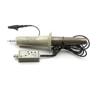
TEKPROBE Interface. The TEKPROBE interface
provides power, signal, and probe characteristic data
transfer.
If your oscilloscope does not support the TEKPROBE
interface, you can use the optional 1103 probe power
supply as an effective interface. Contact your local
Tektronix representative for more information.
 Loading...