Maintenance
2–16
P6015A Instruction Manual
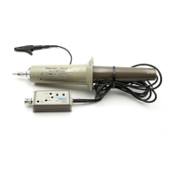
Compensation Box
The compensation box assembly contains three parts that can be
replaced individually: the compensation box/circuit board assembly,
the cable, and the BNC that connects to the oscilloscope or other
instrument. Follow these procedures to replace either the cable or the
BNC, or to install them on a new compensation box. The procedures
are the same in each case.
Removal.
1. Remove the top half of the compensation box.
2. Unsolder the cable (or BNC) center conductor.
3. Unscrew the cable bushing (or BNC).
Replacement.
1. Screw the cable bushing (or BNC) into the end plate.
2. Form the conductor to the solder pad on the circuit board, then
solder the conductor in place.
3. Replace the top half of the compensation box. Note that the
edges are asymetrical (as shown previously in Figure 2–1) and
that the top will seat securely only when it is correctly oriented.
This ensures that the adjustment holes are properly aligned with
the circuit board.