Table of Contents
ii
P6021 Instruction Manual
List of Figures
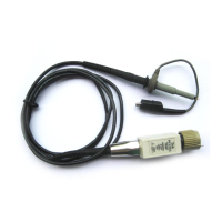
Figure 1: The P6021 Probe and Termination 2. . . . . . . . . . . . . . . . . . . .
Figure 2: Insertion Impedance of the P6021 5. . . . . . . . . . . . . . . . . . . . .
Figure 3: Probe and Termination Input Current vs.
Frequency Derating 9. . . . . . . . . . . . . . . . . . . . . . . . . . . . . . . . . . . . .
Figure 4: Typical P6021 Phase Response 11. . . . . . . . . . . . . . . . . . . . . . .
Figure 5: P6021 Schematic Diagram 13. . . . . . . . . . . . . . . . . . . . . . . . . . .
Figure 6: Connecting the Probe to the Calibration Fixture 18. . . . . . . .
Figure 7: Location of Probe Adjustments 19. . . . . . . . . . . . . . . . . . . . . . .
Figure 8: Location of Termination Adjustments 20. . . . . . . . . . . . . . . . .
Figure 9: Disassembling the Probe 27. . . . . . . . . . . . . . . . . . . . . . . . . . . .
Figure 10: P6021 Probe Component Location 35. . . . . . . . . . . . . . . . . . .
Figure 11: P6021 Termination Component Location 35. . . . . . . . . . . . . .
Figure 12: P6021 Exploded View 41. . . . . . . . . . . . . . . . . . . . . . . . . . . . .
List of Tables
Table 1: Warranted Electrical Characteristics 7. . . . . . . . . . . . . . . . . .
Table 2: Warranted Environmental Characteristics 8. . . . . . . . . . . . . .
Table 3: Maximum Ratings 8. . . . . . . . . . . . . . . . . . . . . . . . . . . . . . . . . .
Table 4: Certifications and Compliances 9. . . . . . . . . . . . . . . . . . . . . . .
Table 5: Electrical Characteristics 10. . . . . . . . . . . . . . . . . . . . . . . . . . . .
Table 6: Mechanical Characteristics 11. . . . . . . . . . . . . . . . . . . . . . . . . . .
Table 7: Equipment List 15. . . . . . . . . . . . . . . . . . . . . . . . . . . . . . . . . . . .

 Loading...


