Performance ver
ification
Input-related spurious response: second converter images
NOTE. You do no
t need to do the first three steps (setup, reset, and alignment) when you perform the input-related spurious
response tests in sequence.
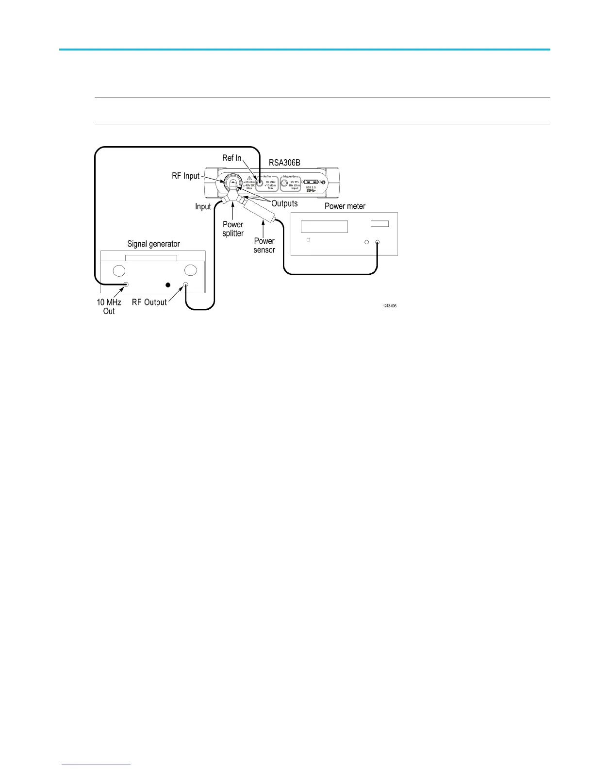
1. Connect the signal generator, power splitter, power sensor, power meter, and RSA306B as shown. Connect the power
sensor and RF si
gnal generator directly to the power splitter, which is connected directly to the RSA306B.
2. Reset the RSA306B to factory defaults (Presets > Main).
3. Run the RSA306B alignment procedure (Tools > Alignments > Align Now).
4. Set the RSA306B as follows:
a. Center frequency = 1GHz
b. Reference Level = –30 dBm
c. Span = 1MHz
d. RBW = 1kHz
e. Detection mode = +PEAK (Setup > Settings > Traces > Detection > +PEAK)
f. Function = Avg (Vrms) (Setup > Settings > Traces > Function)
g. Averaging = 10 (Setup > Settings > Traces > Function: count = 10)
h. Select External Reference (S etup > Acquire > Frequency Reference > External)
5. Set the signal generator frequency to 1.0 GHz.
6. Set the signal generator for –30 dBm at the power meter and RSA306B input. Monitor and set the signal generator
amplitude to -30 dBm at the power meter when changing frequency settings during this test.
7. Measure the CW amplitude at 1 GHz and note it in the second converter image measurements table. (See T
able 17.)
8. Set the signal generator frequency to 1280 MHz.
9. Set the signal generator for –30 dBm at the power meter and RSA306B input.
RSA306B Specifications and Performance Verification 41

 Loading...


