Performance ver
ification
Input-related spurious response: IF feedthrough
NOTE. You do no
t need to do the first three steps (setup, reset, and alignment) when you perform the input-related spurious
response tests in sequence.
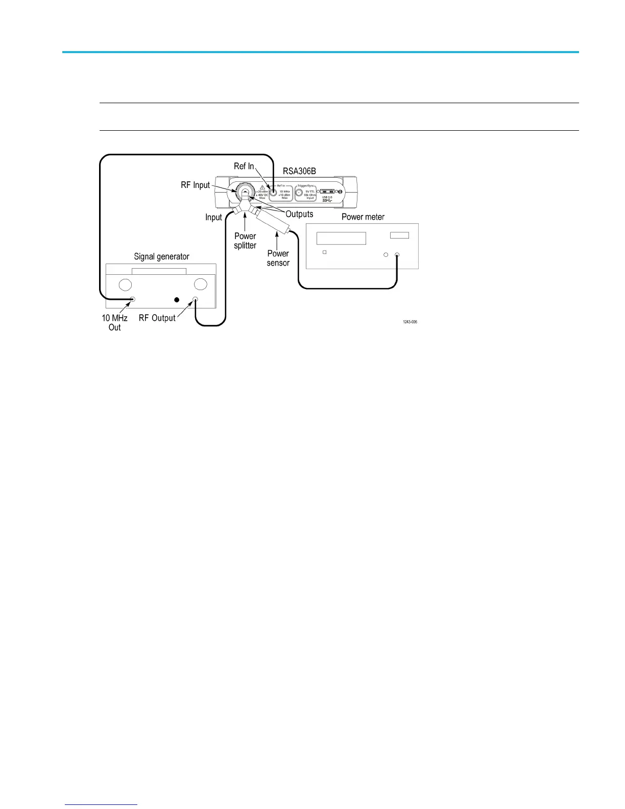
1. Connect the signal generator, power splitter, power sensor, power meter, and RSA306B as shown. Connect the power
sensor and RF signal generator directly to the power splitter, which is connected directly to the RSA306B.
2. Reset the RSA306B to factory defaults (Presets > Main).
3. Run the RSA306B alignment procedure (Tools > Alignments > Align Now).
4. Set the RSA306B:
a. Reference Level = –30 dBm
b. Span =1MHz
c. RBW = 1kHz
d. Detection mode = +PEAK (Setup > Settings > Traces > Detection > +PEAK)
e. Function = Avg (Vrms) (Setup > Settings > Traces > Function)
f. Averaging = 10 (Setup > Settings > Traces > Function: count = 10)
g. Select External Reference (S etup > Acquire > Frequency Reference > External)
1190 MHz IF feedthrough.
5. Set the signal generator to 1190 MHz.
6. Set the signal generator for –30 dBm at the power meter. This is also the amplitude at the input of the RSA306B. The
generator amplitude will be close to –24 dBm.
7. Set the RSA306B to the center frequency shown in the first column of the 1190 MHz IF feedthrough table. (See Table 19
on page 46.)
8. Measure and record the IF feedthrough spur amplitude.
RSA306B Specifications and Performance Verification 45
 Loading...


