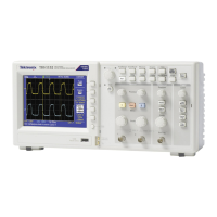
3. Connect the oscilloscope, power supply, and voltmeter as shown in the following figure:
4. Set the power supply to the 1.8 V value shown in column A, the Approximate Test Voltage.
5. Adjust the vertical position knob for the DC line to position the line in the center of the screen.
6. Enter the voltage on the voltmeter and on the oscilloscope into the spreadsheet in the appropriate columns, B and C.
7. Repeat steps 4 through 6 for the values of 1.72 V through 0 V in 0.08 V steps.
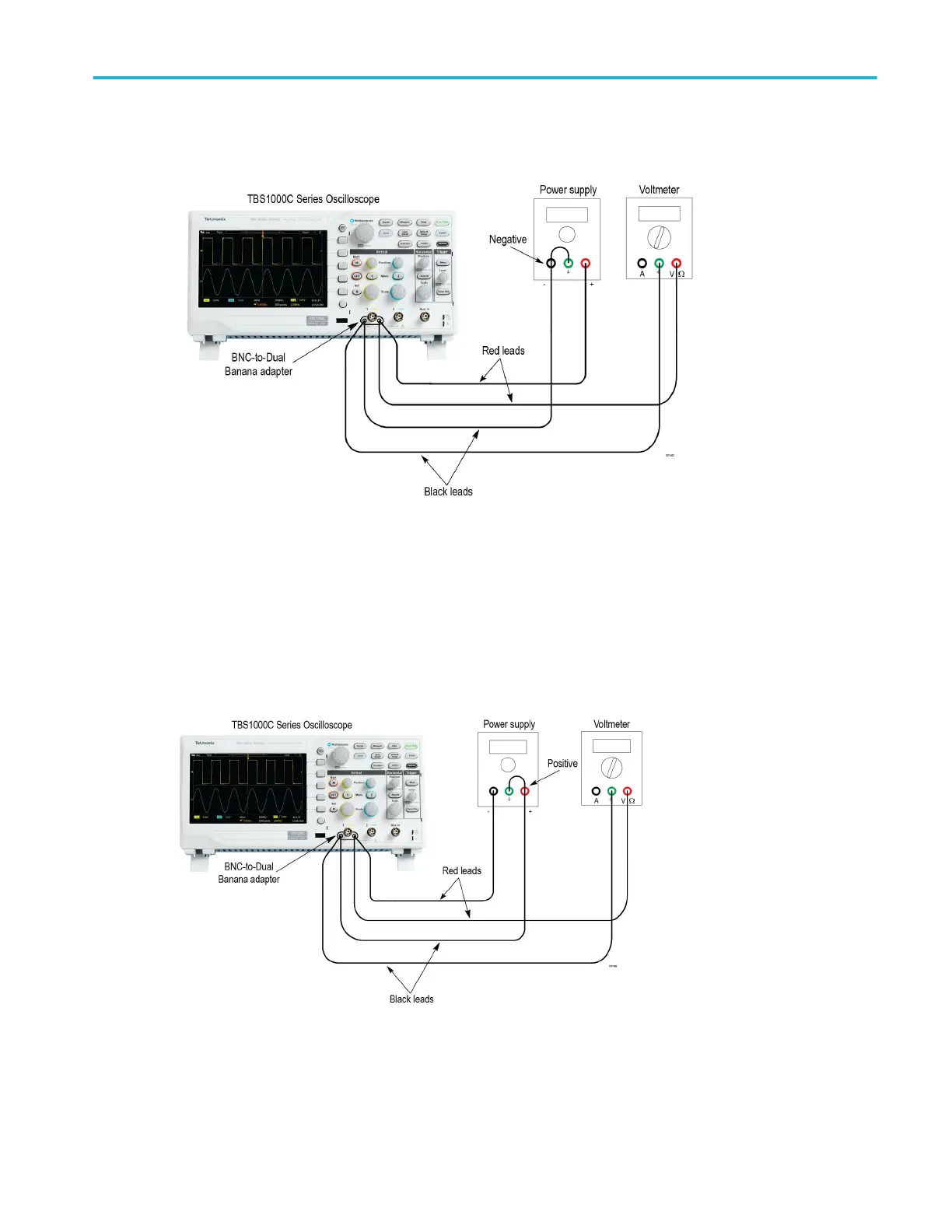
8. Swap the connections to the positive terminal of the power supply with those at the negative terminal as shown in the
following figure:
9. Repeat steps 4 through 6 for the values of -0.08 V through -1.8 V in -0.08 V steps.
10. Enter the Minimum Margin number (cell I16) for the channel tested in the test record.
11. Repeat steps 1 through 10 for all input channels.
Performance verification
TBS1000C Series Specification and Performance Verification 23

 Loading...