Adjustment Procedures
5-12
TDS 420A, TDS 430A & TDS 460A Service Manual
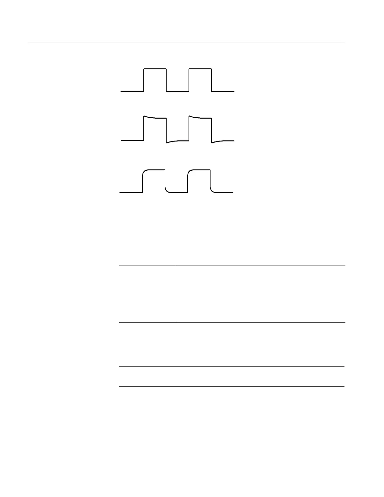
Probe Compensated Correctly
Probe Overcompensated
Probe Undercompensated
Figure 5- 3: Proper and Improper Probe Compensat ion
3. Disconnect the hookup: Disconnect the probe from the probe adj (adjust)
terminals; leave the probe installed on CH 1 and leave the oscilloscope
control setup as is for doing the next part of the probe adjustment.
Equipment
Required
TDS 420A: one leveled sine wave generator (Item 13)
TDS 430A and TDS 460A: one leveled sine wave generator (Item 14)
One BNC female to BNC female adapter (Item 2)
One 50 Ω BNC to probe tip adapter (Item 3)
One P6138A 10X probe (Item 12).
1. Install the test hookup and preset the oscilloscope controls:
a. Expose the Inner Probe Tip: Follow the instructions in F igure 5--4.
NOTE. Refer to the Sine Wave Generator Leveling Procedure on page 4--55 if
your sine wave generator does not have automatic output amplitude leveling.
b. Hook up test-signal source:
H Connect the output of a leveled sine wave generator to a BNC
female to BNC female adapter (see Figure 5--5).
H Connect the BNC female to BNC female adapter to a BNC to probe
tip adapter.
Measure the Probe
Bandwidth

 Loading...


