Typical Characteristics
2–28
TDS 500C, TDS 600B & TDS 700C Performance Verification and Specifications
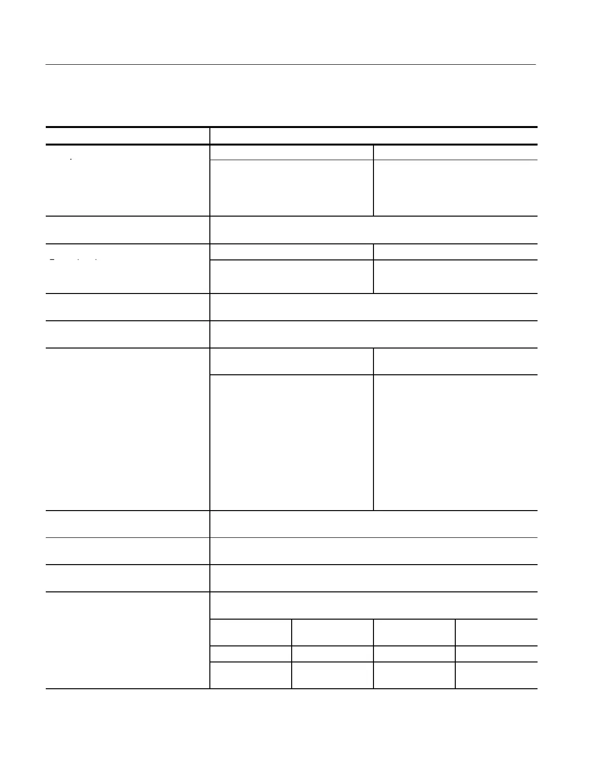
Table 2–17: Typical characteristics — Triggering system
Name Description
u
y,
gg
o
h
sho
d, DC
Trigger source Accuracy
Cou
d
(for signals having rise and fall times
≥ 20 ns)
Any Channel
Auxiliary
±((2% × | Setting – Net Offset |)
+ (0.3 div × Volts/div Setting ) + Offset
Accuracy)
Not calibrated or specified
Input, Auxiliary Trigger
The input resistance is ≥1.5 kW; the maximum safe input voltage is
±20 V (DC + peak AC).
Tr
r P
n
rr
r,
Acquisition mode Trigger-position error
1,2
d
Tr
r
n
Sample, Average
Envelope
±(1 Waveform Interval + 1 ns)
±(2 Waveform Intervals + 1 ns)
Holdoff, Variable, Main Trigger
For all Time/Division ranges, the minimum holdoff is 250 ns and the maximum holdoff is 12
seconds. The minimum resolution is 8 ns for settings ≤ 1.2 ms.
Lowest Frequency for Successful Operation
of “Set Level to 50%” Function
30 Hz
S
n
v
y,
d
Tr
r,
C C
up
d
Trigger source
Typical signal level for stable
triggering
AC
Noise Reject
High Frequency Reject
Low Frequency Reject
Same as the DC-coupled limits for frequen-
cies above 60 Hz. Attenuates signals below
60 Hz.
Three times the DC-coupled limits.
One and one-half times the DC-coupled
limits from DC to 30 kHz. Attenuates signals
above 30 kHz.
One and one-half times the DC-coupled
limits for frequencies above 80 kHz.
Attenuates signals below 80 kHz.
Sensitivities, Logic Trigger and Events
Delay, DC Coupled
4
1.0 division, from DC to 500 MHz, at vertical settings > 10 mV/div and ≤ 1 V/div at the
BNC input
Sensitivities, Pulse-Type Runt Trigger
5
1.0 division, from DC to 500 MHz, at vertical settings > 10 mV/div and ≤ 1 V/div at the
BNC input
Sensitivities, Pulse-Type Trigger Width and
Glitch
6
1.0 division, at vertical settings > 10 mV/div and ≤ 1 V/div at the BNC input
Width, Minimum Pulse and Rearm, for Logic
Triggering or Events Delay
For vertical settings > 10 mV/div and ≤ 1 V/div at the BNC input
Triggering type
Minimum pulse
width
Minimum re-arm
width
Minimum time
between channels
7
Logic Not Applicable 1 ns 1 ns
Events Delay 1 ns (for either + or
– pulse widths)
Not Applicable 2 ns
 Loading...


