Maintenance
6-24
TDS3000B Series Service Manual
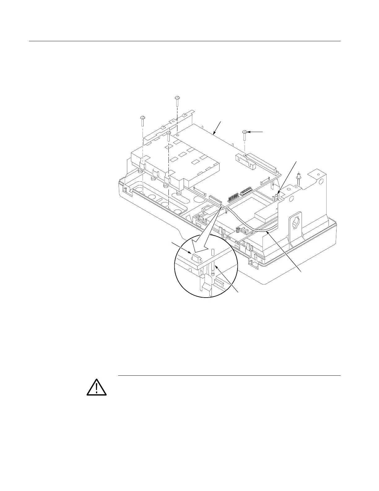
5. UseamagneticTorx® T-15 screwdriver (long bit) to remove the four screws
that secure the main board to the front-panel assembly. See Figure 6--13.
Board snap
Release
board snap
Pogo pin
(CAUTION! Pogo pins are easily
damaged; handle with care. Read
caution note at bottom of this page)
Screws
T-15 (4)
Main board
External
trigger cable
(4-channel
models only)
Figure 6- 13: Main Board
6. R elease the two snaps that hold the main board (see Figure 6--13). Lift the
main board out of the front-panel assembly.
CAUTION. There are a number of small pogo-style pins that extend from the main
board to contact the front chassis. These pins are easily damaged. Use the
following guidelines whenever you handle the main board:
H Always place the main board on your work surface with the pogo pins
facing up
H Do not apply any sideways force on the pogo pins, or slide any objects
across the pogo pins, as they are easily bent
 Loading...
