Operating Information
TDS3000B Series Service Manual
2-19
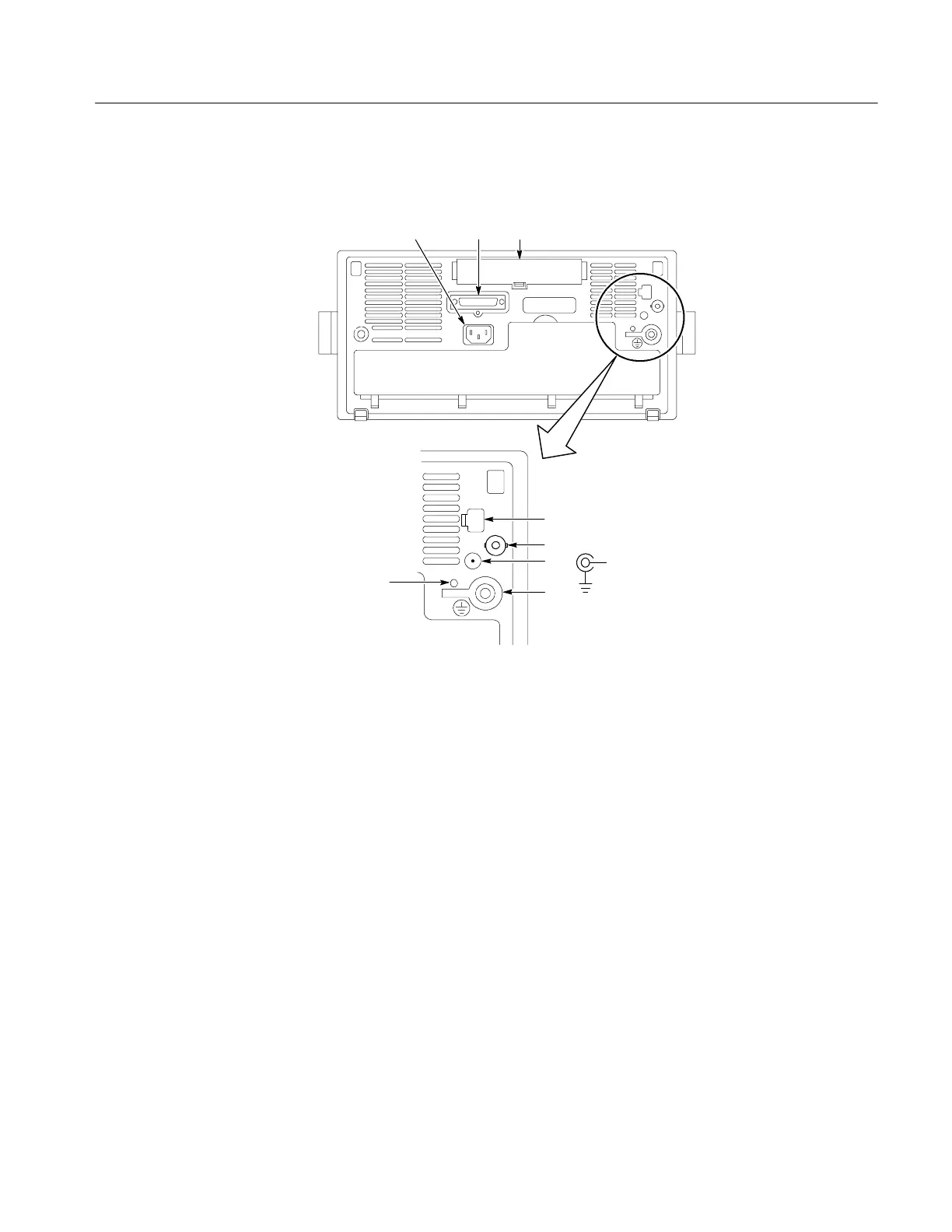
Rear -Panel Connectors
1
5
4
2
6
+14.2 V DC
≤400 mA
3
7
8
1. Power input. Attach to an AC power line with integral safety ground.
2. Parallel printer port. C onnect to a printer to make hard copies.
3. Communication Module compartment. Install optional communication
modules or the t hermal printer.
4. Ethernet port. Connects t he oscilloscope to a 10BaseT local area network.
5. External Trigger input (four-channel models only). See the Specifications
appendix for external trigger signal requirements.
6. DC power output. Provides ~15 V DC power to accessories or to the plug-in
TDS3PRT thermal printer.
7. Ground terminal. Connect to earth ground when using battery power. See
page 2--3 for important safety information.
8. CAL switch. For use by authorized service personnel only.
 Loading...
