Removal and Installation Procedures
TDS7104 & TDS7054 Service Manual
6-- 21
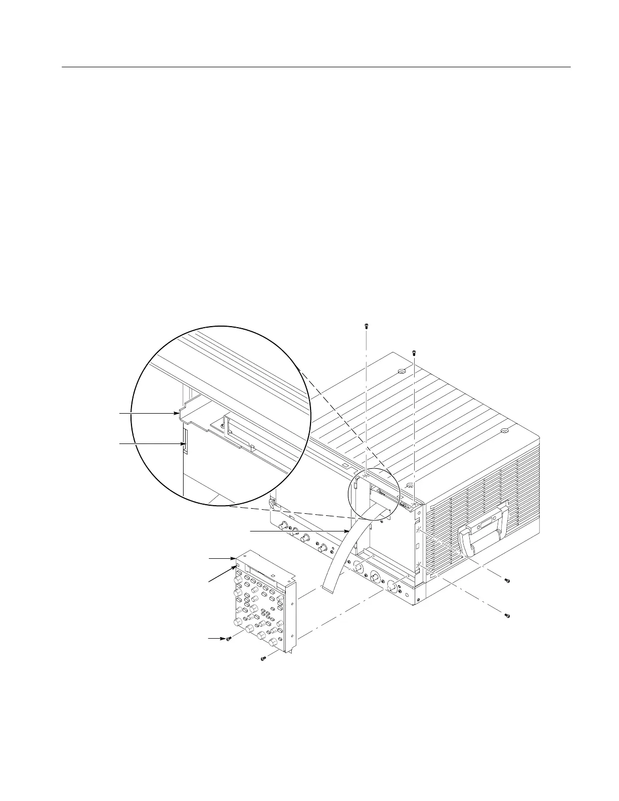
a. Remove the six T-15 Torx screws that secure the Front-panel assembly to
the front chassis.
b. Grasp the top of Front Panel assembly and pull forward to allow access
to the ribbon-cable connector on the front-panel board.
c. Use the
1
@
8
inch flat-bladed screwdriver to carefully lift the J1 cable
connector lock up to disconnect J1 flex cable from the display module
assembly. See Figure 6--10, on page 6--22. Note the connector’s pin 1
index mark and the black stripe on the cable for later reassembly.
d. Pull the Front-Panel assembly forward and remove from the
oscilloscope.
4. Reinstallation: Do in reverse steps a through d to reinstall the front-panel
assembly.
J1 ribbon cable
Front panel
assembly
Front panel square
opening (2)
T--15 Torx
screw (6)
Floppy disk
support tab (2)
Chassis
slot (2)
Figure 6--9: Front-panel assembly removal
 Loading...

