Benchtop Mainframe Removal and Installation Procedures
TLA7000 Series Mainframe Technical Reference Manual
17
NOTE. When reconnecting the blower cables to the chassis, verify that you
connect the b lower cable to J8, 1/BLOWER.
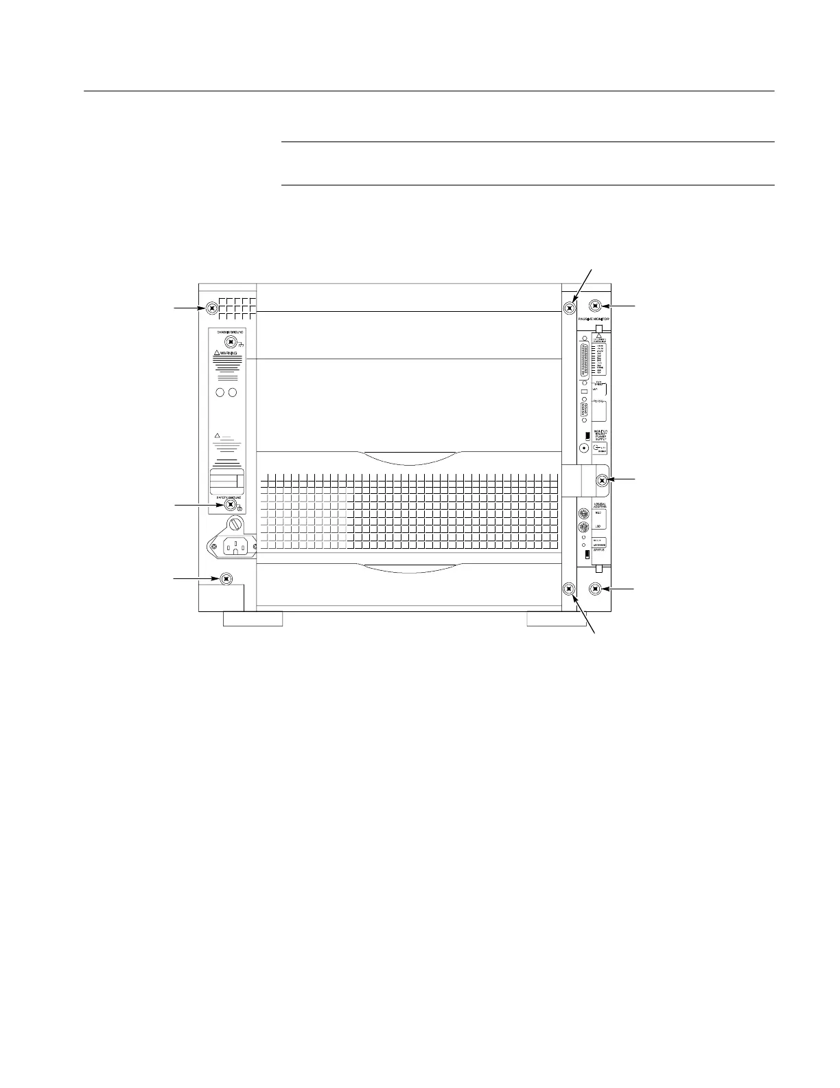
8-32 Captive
screw/fan housing
8-32 Captive
screw/Enhance monitor
8-32 Captive
screw/cable cover
8-32 Captive
screw/fan housing
8-32 Captive
screw/fan housing
8-32 Captive
screw/fan housing
8-32 Captive
screw/Enhance monitor
8-32 Captive
screw/fan housing
Figure 9: Location of blower assembly screws

 Loading...


