System Maintenance—
TM
504
TROUBLESHOOTING
AIDS
Introduction
The
following
is provided
to augment
information
contained elsewhere
in this
and other
TM
500 Series family
manuals
when troubleshooting
becomes necessary.
Circuit
Descriptions
Each
manual has
a
section
devoted
to explaining circuit
operating
theory.
Used conjointly with
the
schematics, this
can
be
a
powerful analytic
tool.
Diagrams
Block
diagrams
and detailed circuit
schematics
are
located
on foldout pages in the
service
section
of most of
the
TM 500 Series family manuals.
The
schematic
diagrams
show the component
values and
assigned circuit
reference
numbers
of
each part necessary
to the circuit
design.
Usually
the first
page of the service
section defines
the
circuit
symbols and reference
designators
used in that
particular instrument.
Major circuits
are usually
identifiable
by
a
series of
component numbers.
Important waveforms
and
voltages
may
be
shown
within the
diagrams
or on
adjoining
aprons.
Those portions
of the circuits
located
on
circuit
boards are
enclosed with
a
blue or grey
tint outline.
Cam Switch
Charts
Cam switches shown
on the diagrams are coded on
comprehensive
charts
to
locate
the
cam
number of the
switch contract
in
the
complete switch assembly,
counting
from
the
front,
or
knob end, toward
the rear
of
the switch.
The charts also
indicate with
a
solid
dot
when each contact
is
closed.
Circuit
Board Illustrations
Line illustrations
showing component
locations
keyed
with
a
grid
scheme for each circuit
board
are usually
placed
on the back
of
a
foldout
page
and sequenced
as
close
as
possible
to an associated schematic.
The
GRID
LOG
columns
located near the
Parts
Location Grid keys
each
component
to easy location
on the
board.
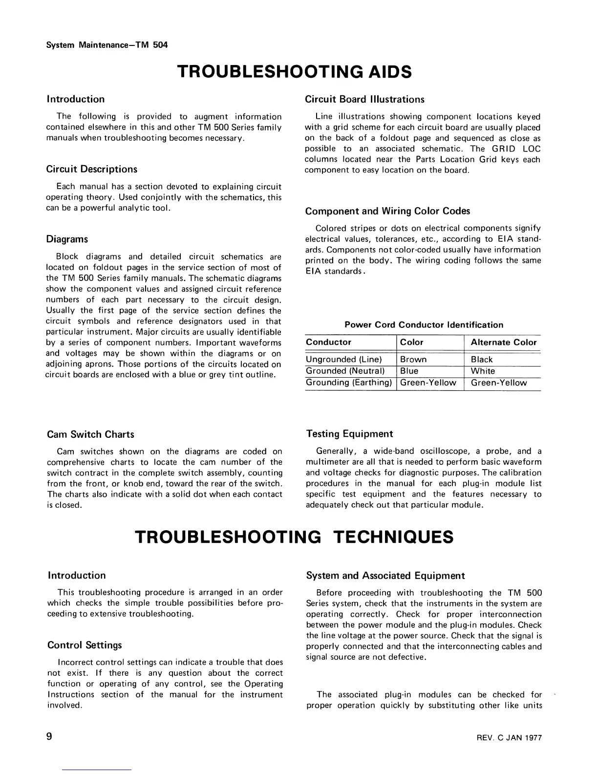
Component
and
Wiring
Color Codes
Colored
stripes or dots on
electrical components
signify
electrical values, tolerances, etc.,
according
to
EIA stand-
ards. Components
not color-coded
usually have information
printed on
the
body.
The
wiring
coding
follows the
same
EIA standards
.
Power
Cord Conductor
Identification
Conductor
Color
Alternate Color
Ungrounded
(Line) Brown
Black
Grounded
(Neutral) Blue
White
Grounding (Earthing)
Green-Yellow
Green-Yellow
Testing Equipment
Generally,
a
wide-band oscilloscope,
a
probe,
and a
multimeter are all that is
needed to perform basic waveform
and voltage checks for diagnostic
purposes. The calibration
procedures in
the
manual for
each plug-in module list
specific
test
equipment
and the features necessary
to
adequately check
out
that particular module.
TROUBLESHOOTING
TECHNIQUES
Introduction
This troubleshooting
procedure
is
arranged
in an
order
which
checks the
simple
trouble possibilities before pro-
ceeding
to
extensive
troubleshooting.
Control Settings
Incorrect control settings can
indicate
a trouble
that
does
not exist. If there is any question
about
the
correct
function
or
operating of any control,
see
the
Operating
Instructions section of the manual
for the instrument
involved.
System
and Associated Equipment
Before
proceeding with troubleshooting
the
TM 500
Series
system, check that the instruments in the
system
are
operating
correctly.
Check for proper interconnection
between the
power module and the plug-in
modules. Check
the line
voltage
at
the power source.
Check that the signal
is
properly
connected
and that
the
interconnecting cables
and
signal
source are
not
defective.
The associated plug-in
modules can
be
checked for
proper operation
quickly
by
substituting other like
units
9
REV.
C
JAN 1977