TM
504
SERVICE
INFORMATION
SYMBOLS
AND REFERENCE
DESIGNATORS
Electrical
components shown on the
diagrams are in the following units unless noted otherwise:
Capacitors
=
Values one or greater are in picofarads
(pF).
Values less than one are in microfarads
(juF).
Resistors
=
Ohms
(^2)
Symbols
used on the
diagrams are based on ANSI
Y32.2
—
1970.
Logic
symbology is based
on
Ml
L-STD-806B
in
terms
of
positive
logic.
Logic symbols
depict the logic
function performed
and
may
differ from
the manufacturer's data.
The
following
special symbols are used on the
diagrams:
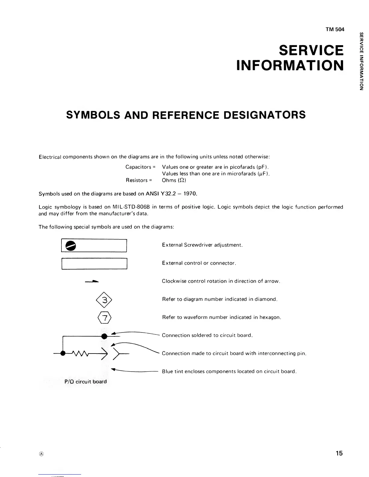
External Screwdriver adjustment.
External
control or
connector.
Clockwise control rotation in direction of arrow.
Refer
to
diagram number indicated in diamond.
Refer
to
waveform number indicated in
hexagon.
Connection
soldered
to
circuit board.
Connection made to circuit
board with interconnecting
pin.
Blue
tint
encloses components located
on
circuit board.
P/0 circuit
board
15
SERVICE
INFORMATION