TCC8900 TCC8900_DEMO_AM_2747_V1.1 July, 31, 2009
Board Guide TCC8900 DEMO BOARD USAGE
Preliminary 2-8
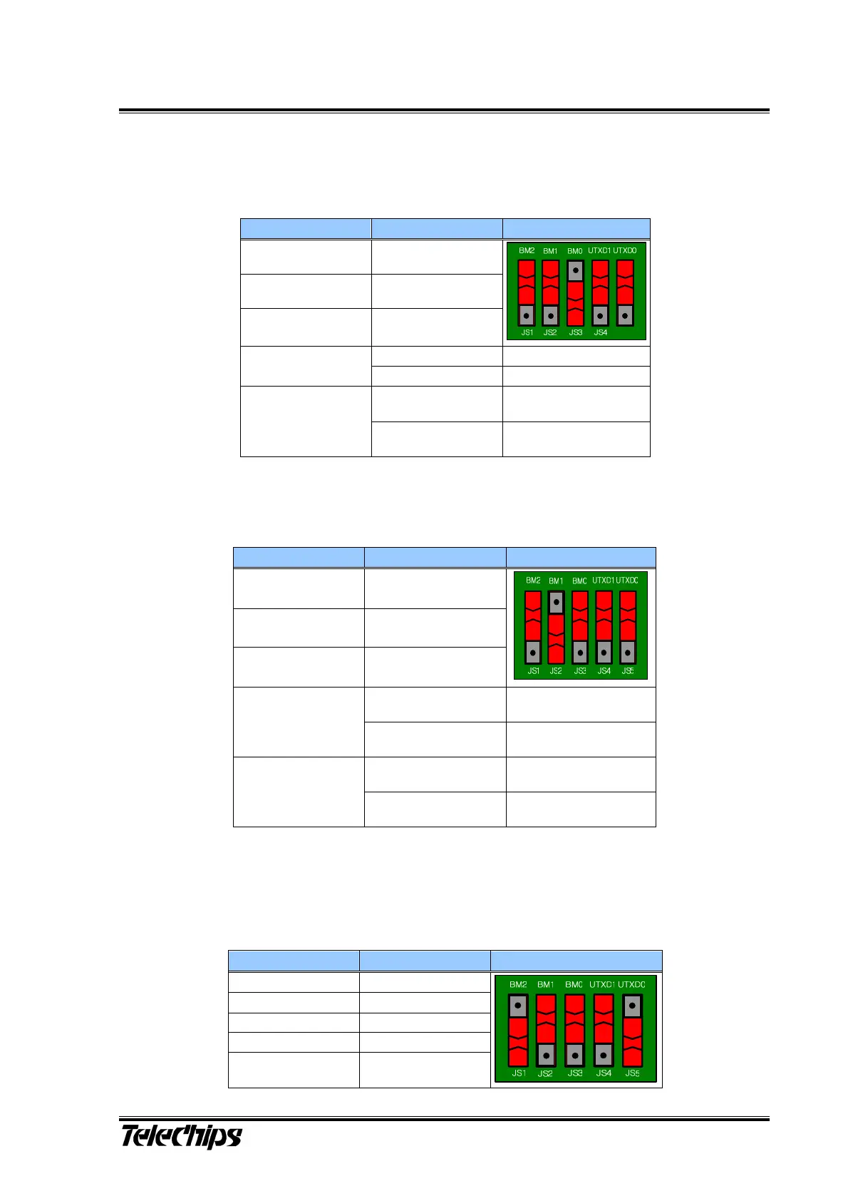
3) Boot from I2C Master (BM[2:0] - 001, UTXD[1:0] - b)
4) Boot from Serial Flash (BM[2:0] - 010, UTXD[1:0] - b)
5) Boot from SPI Slave (BM[2:0] - 100, UTXD[1:0] - b)
Table 3 I2C Master Boot Mode Configurations
Pin Value Figure
BM2(JS1) Low (0)
BM1(JS2) Low (0)
BM0(JS3) High (1)
Low (0) I2C Ch0 Boot
UTXD1(JS4)
High (1) I2C Ch1 Boot
Low (0)
If I2C boot fails,
UART Ch0 boot starts.
UTXD0(JS5)
High (1)
If I2C boot fails,
UART Ch1 boot starts.
Table 4 Serial Flash Boot Mode Configurations
Pin Value Figure/Comment
BM2(JS1) Low (0)
BM1(JS2) High (1)
BM0(JS3) Low (0)
Low (0)
If Serial flash boot fails,
UART boot starts
UTXD1(JS4)
High (1)
If serial flash boot fails,
USB boot starts
Low (0)
In UART boot,
UART channel is 0.
UTXD0(JS5)
High (1)
In UART boot,
UART channel is 1.
Table 5 SPI Slave Boot Mode Configurations
Pin Value Figure
BM2(JS1) High (1)
BM1(JS2) Low (0)
BM0(JS3) Low (0)
UTXD1(JS4) Don’t care
UTXD0(JS5) High (1)