TCC8900 TCC8900_DEMO_AM_2747_V1.1 July, 31, 2009
Board Guide TCC8900 DEMO BOARD USAGE
Preliminary 2-9
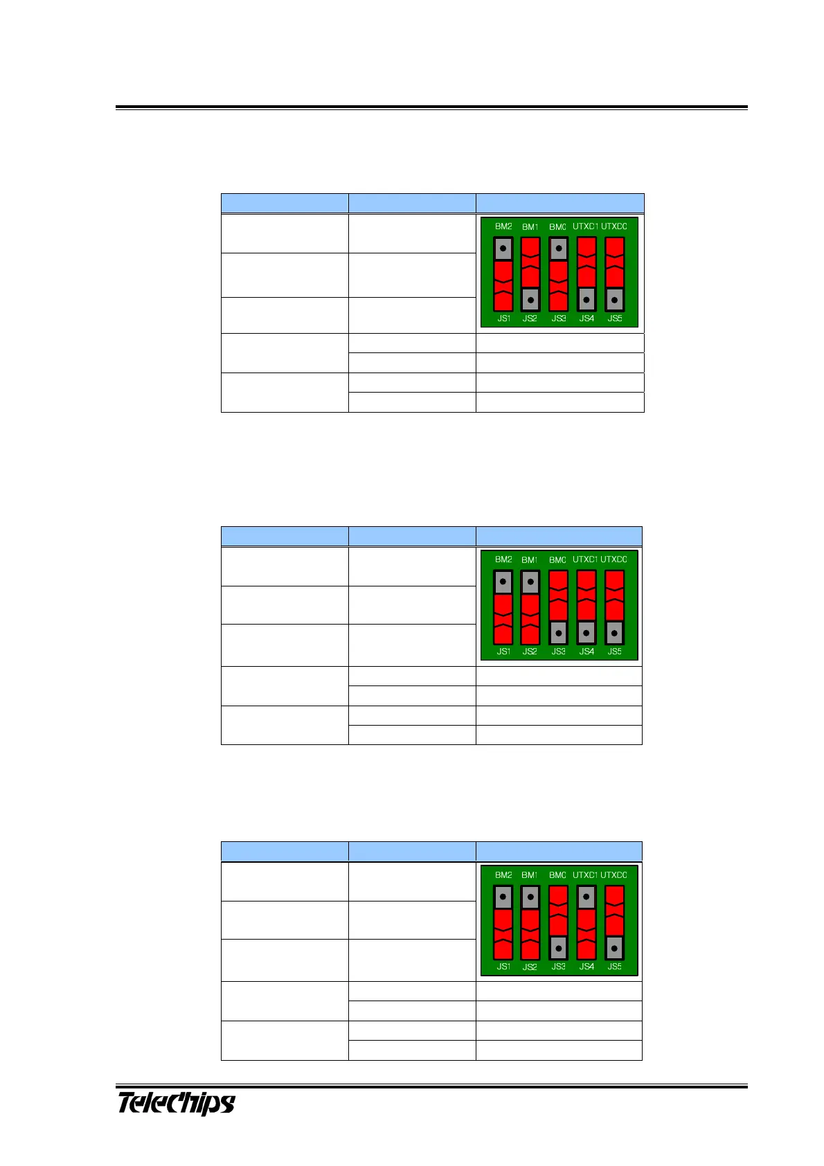
6) Boot from SD/MMC (BM[2:0] - 001, UTXD[1:0] - b)
7) Boot from NOR Flash (BM[2:0] - 011, UTXD[1:0] - b)
8) Boot from UART (BM[2:0] - 011, UTXD[1:0] - b)
Table 6 SD/MMC Boot Mode Configurations
Pin Value Figure
BM2(JS1) High (1)
BM1(JS2) Low (0)
BM0(JS3) High (1)
Low (0) SD/MMC Ch0 Boot
UTXD1(JS4)
High (1) SD/MMC Ch1 Boot
Low (0)
Bus width 4bit
UTXD0(JS5)
High (1)
Bus width 1bit
Table 7 NOR Flash Boot Mode Configurations
Pin Value Figure
BM2(JS1) High (1)
BM1(JS2) High (1)
BM0(JS3) Low (0)
Low (0)
UTXD1(JS4)
Low (0)
Low (0)
Bus width 8bit
UTXD0(JS5)
High (1)
Bus width 16bit
Table 8 NOR Flash Boot Mode Configurations
Pin Value Figure
BM2(JS1) High (1)
BM1(JS2) High (1)
BM0(JS3) Low (0)
Low (0)
UTXD1(JS4)
Low (0)
Low (0) UART Ch0 Boot
UTXD0(JS5)
High (1) UART Ch1 Boot