TCC8900 TCC8900_DEMO_AM_2747_V1.1 July, 31, 2009
Board Guide TCC8900 DEMO BOARD USAGE
Preliminary 2-13
Figure 10. CPU I/F LCD Switch Setting
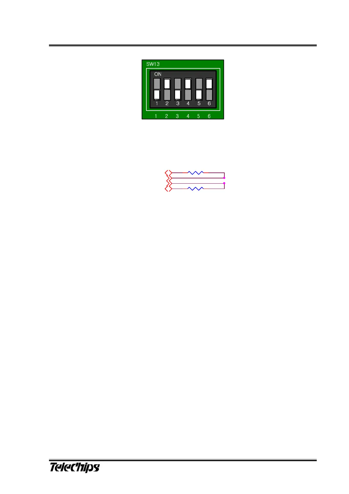
그러나 18bit CPU 방식의 LCD는 사용할 경우에는 아래 그림과 같이 LCD Interface Header Parts
에 구성되어 있는 Resistor를 변경하면 된다.
R290 0
R289 0
LCD_CLK
LCD_VS
LCD_D16
LCD_D17
Figure 11. 18bit CPU I/F LCD Resistor Setting