Home
TeleChips
Motherboard
TCC8900
Page 7 (Figure 2. Tcc8900 Demo V1.X Board Description)
TeleChips TCC8900 - Figure 2. Tcc8900 Demo V1.X Board Description; Figure 3. Tcc8900 Cpu Board Description
29 pages
Manual
Save Page as PDF
To Next Page
To Next Page
To Previous Page
To Previous Page
Loading...
T
CC8900
TCC8900_DEMO_AM_2747_V1.1
July
, 31, 2009
Board Guide
TCC8900 DEMO BO
ARD PIN DESCRIPTION
Preliminary
1-2
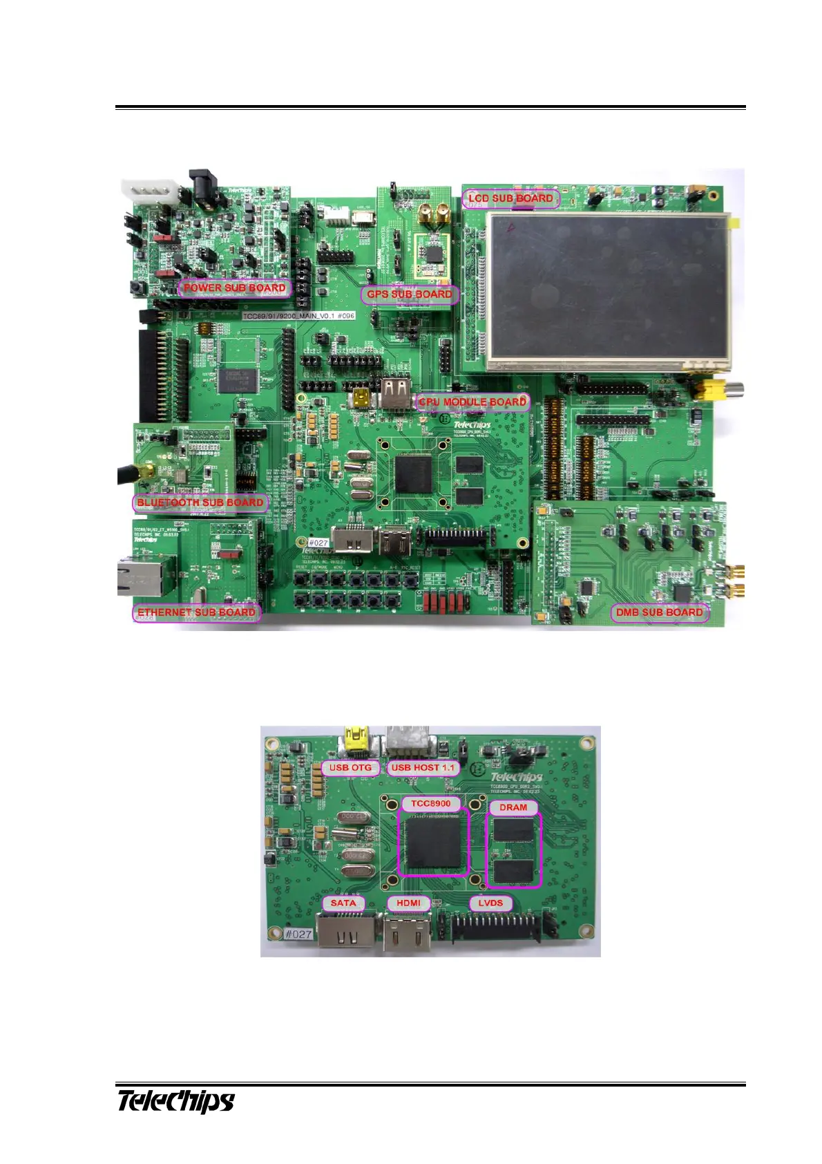
1.2 TCC8900_DEMO(CPU+MAIN) V1.x Bo
ard Description
Figure 2. TCC8
900 DEMO V
1.x Board Descri
ption
Figure 3. TCC8
900 CPU Boar
d Description
6
8
Table of Contents
Main Page
Default Chapter
4
Table of Contents
4
1 TCC8900 Demo Board Pin Description
6
Figure 1. Tcc8900 Demo Board Block Diagram
6
Figure 2. Tcc8900 Demo V1.X Board Description
7
Figure 3. Tcc8900 Cpu Board Description
7
Figure 4. Tcc8900 Main Board Description
8
Figure 5. Jumper Cap Connection
11
2 TCC8900 Demo Board Usage
12
Jumper Setting Mode
12
Boot Mode Selection
12
Table 1 Usb Boot Mode Configurations
12
Table 2 Nand Boot Mode Configurations
12
Table 3 I2C Master Boot Mode Configurations
13
Table 4 Serial Flash Boot Mode Configurations
13
Table 5 Spi Slave Boot Mode Configurations
13
Table 6 Sd/MMC Boot Mode Configurations
14
Table 7 nor Flash Boot Mode Configurations
14
Table 8 nor Flash Boot Mode Configurations
14
SD&MMC / MS(Memory Stick) Card Selection Mode
15
Table 9 Ehi Boot Mode Configurations
15
Table 10 Sd(MMC)/Ms Selection
15
NAND_CE# Setting
16
Figure 6. Nand_Ce# Setting
16
Figure 7. Sw12 Setting
16
LCD I/F Switch Setting
17
LCD I/F Switch Setting of RGB Interface
17
LCD I/F Resistor Setting of CPU Interface
17
Figure 8. Lcd I/F Setting
17
Figure 9. Rgb I/F Lcd Switch Setting
17
Figure 10. Cpu I/F Lcd Switch Setting
18
Figure 11. 18Bit Cpu I/F Lcd Resistor Setting
18
Resistor Setting in the Non-Use of JTAG
19
Figure 12. Resistor Setting in the Non-Use of Jtag
19
Switch Setting for Interface Function Select
20
Table 11. I-Pod / Uart Selection
20
3 TCC8900 Demo Board Revisions (V1.1)
24
HDMI CEC (CPU Module)
24
Voltage Level Shift for the HDMI EDID (CPU Module)
24
Figure 13. Hdmi Cec Control (Sv1.1)
24
Figure 14. Circuit of Hdmi Edid with Chipset (Sv1.0)
25
Figure 15. Circuit of Hdmi Edid with the Fet (Sv1.1)
25
SD1 Card (Main)
26
GPIO Expander (Main)
26
Figure 16. Sd1 Card I/F (V1.1)
26
Figure 17. Gpio Expander (V1.1)
26
4 TCC8900 Demo Board Revisions (V1.2)
27
TCC8901/8902 (Main)
27
Figure 18. Power Header for Tcc8901/02 (V1.2)
27
NAND V2 Boot Mode (Main)
28
Figure 20. after Ax Version Chipset (New)
29