BioOptix™ 10
Section 2 Installation
2-4
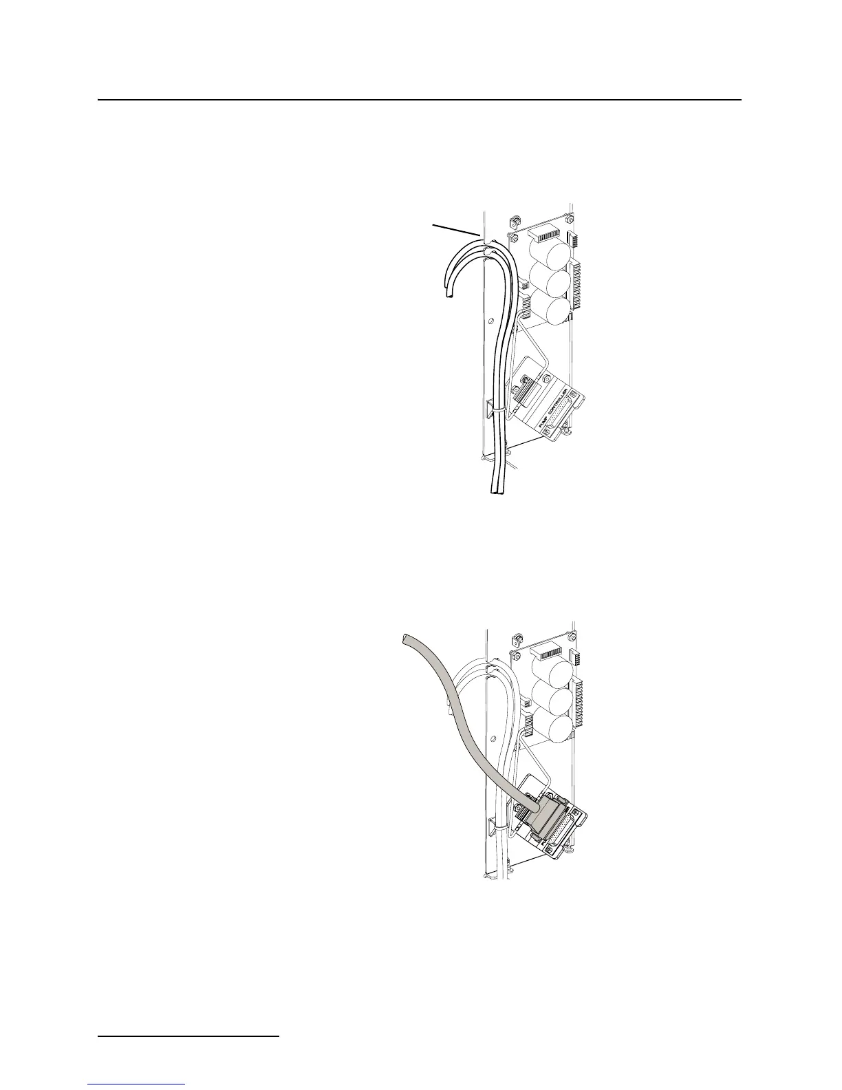
3. While facing the back of the column module, locate the two
liquid tubing bundles secured to the lower-left inside case
panel. Route these two bundles through the slots at the
edge of the panel (Figure 2-4).
Figure 2-4 Routing the Sample Out lines (column
module)
4. Connect the beige 25-pin connector from the pump module
to the column module connector labeled Pump Controller.
Refer to Figure 2-5.
Figure 2-5 Pump controller connection
Route tubing
through slots
To
Foxy 200
From Pump
Module