BioOptix™ 10
Section 4 System Maintenance
4-3
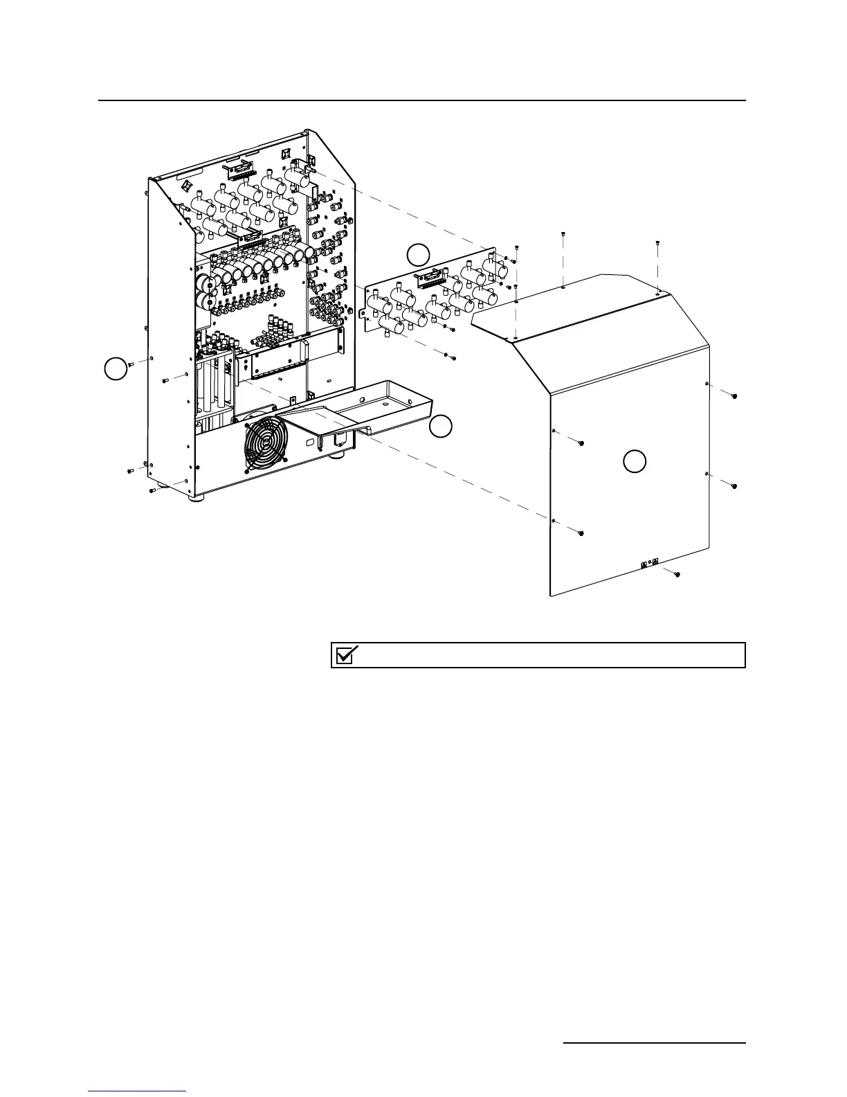
Figure 4-2 Access the pump assembly
Note
Refer to Figure 4-3 for the following steps.
9. Remove the bottom retainer plate.
10. On the top of the pump assembly, remove the two
10-32 ×
3
/8" pan head screws and lock washers.
11. Lift the piston plug and top O-ring from the glass cylinder.
12. Remove the glass cylinder and bottom O-ring. This exposes
the push rod and seal.
13. The push rod shaft has two slots for a wrench. Hold the
push rod at the slots with a
3
/16" wrench and remove the #6
screw and washers from the bottom of the push rod.
14. Lift the push rod out of the assembly.
15. Using care to avoid damaging the push rod, cut the seal
with a sharp blade. Then, pull the seal off the push rod.
16. Place the replacement seal upside-down on a firm, flat sur-
face (Figure 4-4).
1
2
3
4


 To Next Page