ii
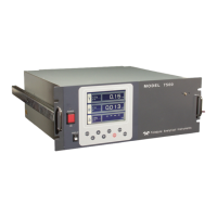
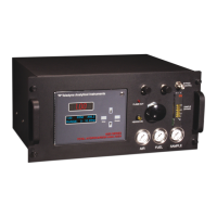
Model 7320 Infrared Gas Analyzer
Teledyne Analytical Instruments
Table of Contents
1 Introduction
1.1 Overview ........................................................................ 1-1
1.2 Typical Gas Applications................................................ 1-1
1.3 Main Features of the Analyzer ....................................... 1-2
1.4 General .......................................................................... 1-3
1.5 NDIR Analyzer ............................................................... 1-3
1.6 Operator Interface (Front Panel ...................................... 1-4
1.6.1 UP/DOWN Switch ................................................. 1-4
1.6.2 ESCAPE/ENTER Switch ...................................... 1-5
1.7 Difference Between LCD & VFD .................................... 1-5
1.8 Equipment Interface ....................................................... 1-5
1.9 Gas Connections ........................................................... 1-6
2 Installation
2.1 Unpacking the Analyzer................................................. 2-1
2.2 Installing & Connecting the Analyzer ............................. 2-1
2.2.1 User Connections ................................................. 2-2
2.2.2 Electrical Power Connections ............................... 2-2
2.2.3 Calibration Gases ................................................. 2-2
2.2.4 Pipe Connection ................................................... 2-3
2.2.5 Sample Delivery System ....................................... 2-3
2.2.6 Venting the System ............................................... 2-3
2.3 Electrical Connections (rear Panel) ............................... 2-3
2.3.1 Primary Input Power .............................................. 2-4
2.3.2 Fuse Installation .................................................... 2-4
2.3.3 Terminal Block Connections ................................. 2-4
2.3.3.1 Analog Outputs .............................................. 2-5
2.3.3.2 Alarm Relays ................................................. 2-6
2.3.3.3 Digital Remote Cal Input................................ 2-8
2.3.3.4 Range ID Relays ........................................... 2-9
2.3.3.5 Network I / O .................................................. 2-10
2.3.3.6 Remote Valve Connector ............................... 2-10
2.3.4 RS-232 Port .......................................................... 2-11
2.4 Gas Requirements ......................................................... 2-12



 To Next Page