BlueMod+S50 Hardware User Guide
1VV0301505 Rev. 1 Page 14 of 53 2018-03-02
Reset
BlueMod+S50 are equipped with circuitry for generating reset from two sources:
• A reset is held active, when VSUP falls below the threshold of the brownout detector (V
BOR
=
1,2V … 1,7V), and is released when VSUP rises above V
BOR
+ V
HYST
.
The brownout detector also holds the reset active during power up, until VSUP > V
BOR
.
• A reset is generated, when VSUP is > V
BOR
and increases 300 mV or more, within 300 ms
or less.
• By holding pin B-1 (EXT-RES#) at ≤ VSUP*0,25V for t
HOLDRESETNORMAL
≥ 0,2µs, an external
reset (pin reset) is generated. This pin has a fixed internal pull-up resistor (R
PU
= 11kΩ ...
16kΩ). EXT-RES# may be left open if not used.
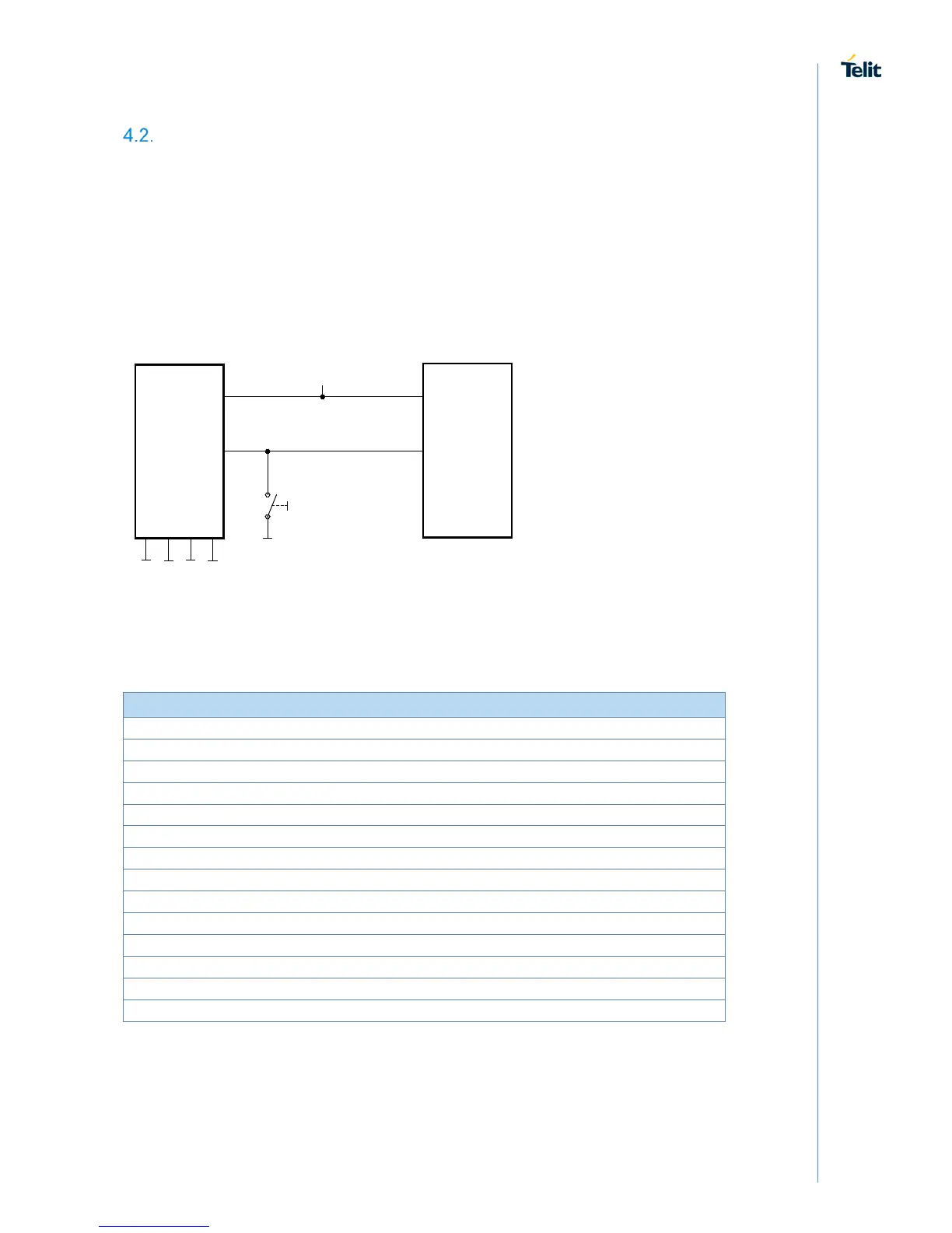
BlueMod+S50
E-6,F-6
VSUP
GND
+3V3
EXT-RES#
B-1
Reset-Switch is optional
Please Note: EXT-RES# of BlueMod+S50 has approx. 13k internal pullup.
Reset signal is optional
Host MCU
GPIO
VDD
Figure 4: BlueMod+S50 Example Reset
The following table shows the pin states of BlueMod+S50 during reset active. This pin
states are kept until hardware initialization has started.
EXT-RES# Input with pull-up
(1)
XL-IN Input floating (disconnected)
XL-OUT Input floating (disconnected)
UART-TXD Input floating (disconnected)
UART-RXD Input floating (disconnected)
UART-RTS# Input floating (disconnected) with pull-up resistor 470kΩ
(2)
UART-CTS# Input floating (disconnected)
IUR-OUT# Input floating (disconnected)
IUR-IN# Input floating (disconnected)
Input floating (disconnected)
TESTMODE# Input floating (disconnected)
BOOT0 Input floating (disconnected)
SWDIO Input with pull-up
(1)
SWCLK Input with pull-down
(1)
(1)
pull-up, pull-down: R
PU,
R
PD
is typ. 10kΩ
Table 1: Pin States during Reset

 Loading...