BlueMod+S50 Hardware User Guide
1VV0301505 Rev. 1 Page 20 of 53 2018-03-02
Serial Wire Debug Interface
The Serial Wire Debug (SWD) interface (signals SWDIO, SWCLK) is normally not used in
a customer’s product. It is reserved for debugging purposes.
Leave SWDIO, SWCLK unconnected. Only if you intend to use them for debugging
purposes, make them available.
Test Mode
For regulatory approval purposes, the ability of test mode operation like “BlueMod+S50
Testmode” or “Direct two wire UART Testmode” (DTM) is mandatory. The Direct Test Mode
(as defined by the Bluetooth SIG) and BlueMod+S50 Testmode are part of the
BlueMod+S50 firmware. Please refer to [6] & [7].
For enabling the different test modes the BlueMod+S50 provides two IO pins.
• The pin Testmode is low active. Active means connect to GND.
• The pin Boot0 is high active. Active means connect to VSUP.
• The other two combinations start the bootloader for firmware update of the
programmed firmware. These two modes are not scope of this document.
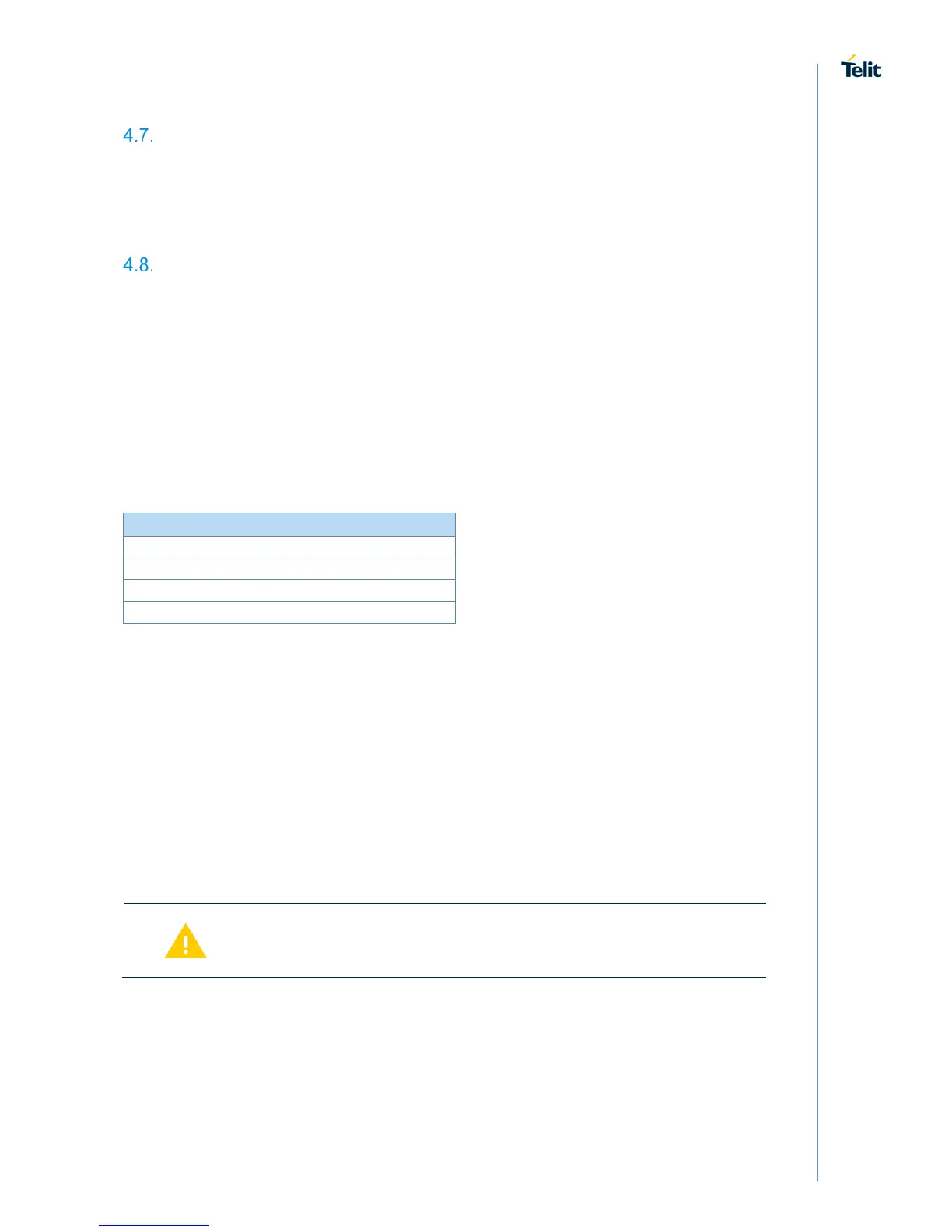
Table 3 shows the possible combinations:
Table 3: Testmode# / Boot0 Logic
To enter and use the test modes, access to the following signals is required:
• BOOT0
• TESTMODE#
• UART-RXD
• UART-TXD
• UART-RTS#
• UART-CTS#
• GND
These pins shall be routed to some test pads on an outer layer, but can be left open during
normal operation when not used.
Please note the UART is required for operation of DTM. For any
regulatory approval, UART-RXD, UART-TXD, UART-RTS# and
UART-CTS# must be freely accessible.

 Loading...