GE910 Hardware User Guide
1vv0300962 Rev.12 2013-10-22
Reproduction forbidden without Telit Communications S.p.A. written authorization - All Rights Reserved
page 50 of 83
Mod. 0805 2011-07 Rev.2
10. Serial Ports
The serial port on the GE910 is the core of the interface between the module and OEM hardware.
3 serial ports are available on the module:
• MODEM SERIAL PORT 1 (Main)
• MODEM SERIAL PORT 2 (Auxiliary)
• MODEM SERIAL PORT 3 (NMEA on GE910-GNSS products).
10.1. Modem Serial Port
Several configurations can be designed for the serial port on the OEM hardware, but the most
common are:
• RS232 PC com port
• microcontroller UART
@
1.8V (Universal Asynchronous Receive Transmit)
• microcontroller UART
@
3V or other voltages different from 1.8V
• microcontroller UART
@
5V or other voltages different from 1.8V
The serial port on the GE910 is a +1.8V CMOS UART with all the 8 RS232 signals. It differs
from the PC-RS232 in the signal polarity (RS232 is reversed) and levels.
For system working on different digital supply standard, a level translator circuit may be needed
to make the system work properly.
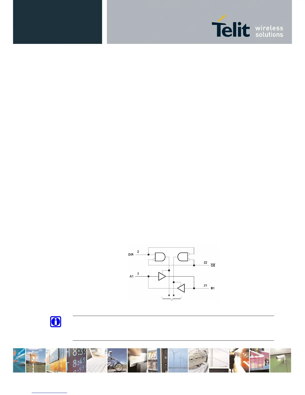
An Example of level translation implementation could be the use of a standard 74LVC245, a
Dual-Supply Bus Transceiver, which Logic Diagram is shown here:
To other Channels
NOTE:
OE connected to VAUX pin may be a useful solution to avoid Back-Powering by means of
disabling the bus, not to supply a voltage level, while modem is OFF.