1VV0301078 Rev.10 – 2015-11-11
Reproduction forbidden without written authorization from Telit Communications S.p.A. - All Rights Reserved. Page 21 of 88
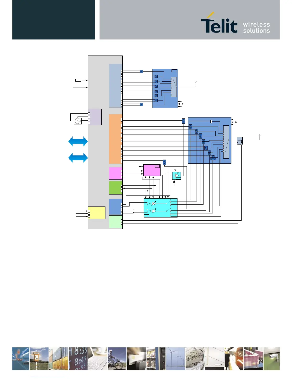
This section describes the signals available to the host processor at the 75 pin application
interface. Eight signals are eliminated by the notch on the host connector, leaving 67 usable
signals. A diagram of the M.2 module identifying the 75 pin interface is shown in Figure 5.
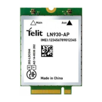
Note that the M.2 module has all components mounted on the top side. Odd pin numbers are on the top
side while even pins on the bottom side.