This document is the property of Telma. It cannot be copied, forwarded, or given to any party without prior agreement form TELMA. Any infringement will immediately involve legal action.
TELMA S.A., 28 rue Paul Painlevé, F-95310 Saint-Ouen l’Aumône - www.telma.com 17 / 18 OC441691
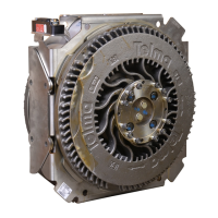
After having adjusted the air gaps, on each
retarder side, unscrew the removed shaft end
screws and the removed pressure plate.
Install 2 new shaft end screws and a new pressure
plate supplied with the replacement hub assembly.
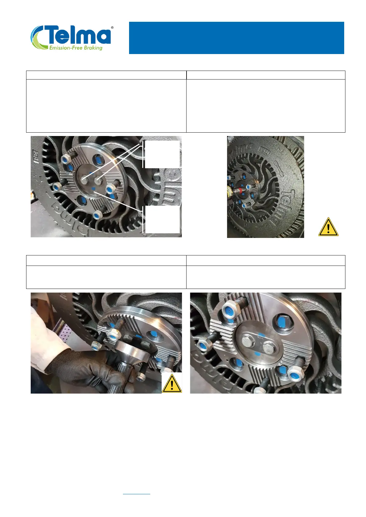
With a manual torque wrench, apply a tightening
torque value of 60 Nm ± 20% (44 lb.ft ± 20%)
alternately on these 2 screws.
Use a locking bar to be inserted inside a rotor
cooling canal for preventing the rotation of the
rotor.
Insert a new lock tab in the retaining tab driver
On each retarder side, put in place the lock tab
over the screw heads and hit with a hammer.
Check that the lock tabs are well bottomed over
the shaft end screw heads.