TEMPMASTER
20
FORM TPM3-EG1 (518)
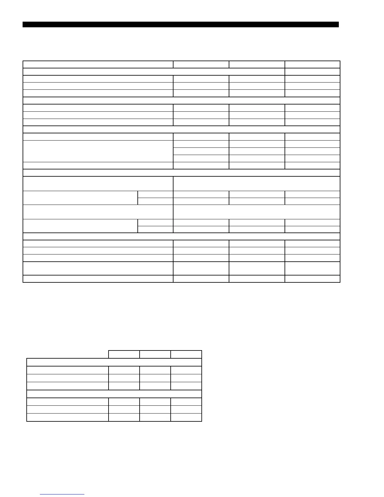
TABLE 4 - REFRIGERANT CHARGE DATA
120 130 150
REFRIGERANT CHARGE (STD CABINET)
SYS 1 - lb (kg) 41 (18.6) 41 (18.6) 41 (18.6)
SYS 2 - lb (kg) 73 (33.1) 82 (37.2) 77 (34.9)
SYS 3 - lb (kg) 97 (44.0) 98 (44.4) 106 (48.1)
REFRIGERANT CHARGE (EXTD CABINET)
SYS 1 - lb (kg) 43 (19.5) 43 (19.5) 43 (19.5)
SYS 2 - lb (kg) 75 (34.0) 84 (38.1) 79 (35.8)
SYS 3 - lb (kg) 100 (45.4) 101 (45.8) 109 (49.4)
MODEL SIZE 120 130 150
FILTERS - 2-INCH CARBON (PRE-FILTER POSITION) (MERV 7)
Quantity 36/12 36/12 36/12
Size (length x width in inches) 16x20/20x20 16x20/20x20 16x20/20x20
Total Filter Face Area (sq. ft.) 113.3 113.3 113.3
FILTERS - 12-INCH RIGID 65%, 2-INCH 30% PREFILTER (PRE-FILTER POSITION) (MERV 11)
Quantity 7/21 7/21 7/21
Size (length x width in inches) 20x16/20x25 20x16/20x25 20x16/20x25
Total Filter Face Area (sq. ft.) 88.5 88.5 88.5
FILTERS - 12-INCH RIGID 95% (FINAL FILTER POSITION) (MERV 14)
Quantity 5/3/3/4/6/7 5/3/3/4/6/7 5/3/3/4/6/7
Size (length x width in inches)
12x24,16x20 12x24,16x20 12x24,16x20
16x25, 20x20 16x25, 20x20 16x25, 20x20
20x24, 20x25 20x24, 20x25 20x24, 20x25
Total Filter Face Area (sq. ft.) 80.4 80.4 80.4
GAS FURNACE
Staged Furnace Sizes
(input/output/stages)
1125 mbh/900 mbh/6 stages
Gas Pressure Range (min. to max. iwg)
Natural 4.5–10.5 inch w.c. 4.5–10.5 inch w.c. 4.5–10.5 inch w.c.
Propane 11.0–13.0 inch w.c. 11.0–13.0 inch w.c. 11.0–13.0 inch w.c.
Modulating Furnace Sizes
(input/output/turndown)
1125 mbh/900 mbh/24:1 turndown
Gas Pressure Range (min. to max. iwg)
Natural 4.5–10.5 inch w.c. 4.5–10.5 inch w.c. 4.5–10.5 inch w.c.
Propane 11.0–13.0 inch w.c. 11.0–13.0 inch w.c. 11.0–13.0 inch w.c.
ELECTRIC HEATERS
Size Range (min. to max. kW) 80-250 80-250 80-250
Heating steps
1
2-6 2-6 2-6
Minimum steps
1
2 2 2
MINIMUM OUTSIDE AIR (OA)TEMPERATURE FOR
MECHANICAL COOLING
50 50 50
LOW AMBIENT OPTION MIN. OA TEMP 0 0 0
NOTES
1. Electric heat steps and airow range depends on voltage and size. Consult the air pressure drop tables for specic number of steps for a
given voltage.
TABLE 3 – PHYSICAL DATA – MODELS 120-150 (CONT'D)
Physical Data (Cont'd)