57
TEMPMASTER
FORM TPM3-EG1 (518)
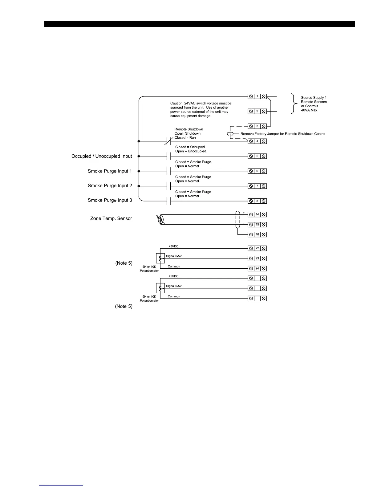
Field Control Wiring
FIGURE 8 - FIELD CONTROL WIRING - INPUTS
LD08184C
Supply Air Temp. Setpoint Reset
25
26
22
DSP- (DUCT STATIC RESET -)
DSP+ (DUCT STATIC RESET +)
+5V (DUCT STATIC SP + 5V)
+5V (SAT SP + 5V)
SHLD - (SHIELD (GND))
ZR - (ZONE TEMP SENSOR -)
ZR + (ZONE TEMP SENSOR +)
SMK3 - (SMOKE PURGE 3)
SMK2 - (SMOKE PURGE 2)
SMK1 - (SMOKE PURGE 1)
OCC - (OCCUPIED/UNOCCUPIED)
SD - (SHUTDOWN)
24V - (24VAC)
24V -
(24VAC)
COM -
(24VAC
COM)
SAT - (SUPPLY AIR TRMP RESET -)
SAT + (SUPPLY AIR TRMP RESET +)
1
or
Duct Pressure Setpoint Reset
Or
Supply Fan Sync Command
NOTES:
1. Wiring shown indicates typical wiring. Refer to the Installation, Operation, and Maintenance (IOM) manual (Form TPM3-NOM1) for more
detailed wiring methods and options
2. All wiring is Class 2, low voltage.
3. Maximum power available from the 24VAC terminal is 40VA.
4. Use shielded wire where shown.
5. Potentiometer application shown. As an alternative, signal inputs can be driven from an analog output of a third party controller.
*Input resistance is 15 K ohms.