TEMPMASTER
56
FORM TPM3-EG1 (518)
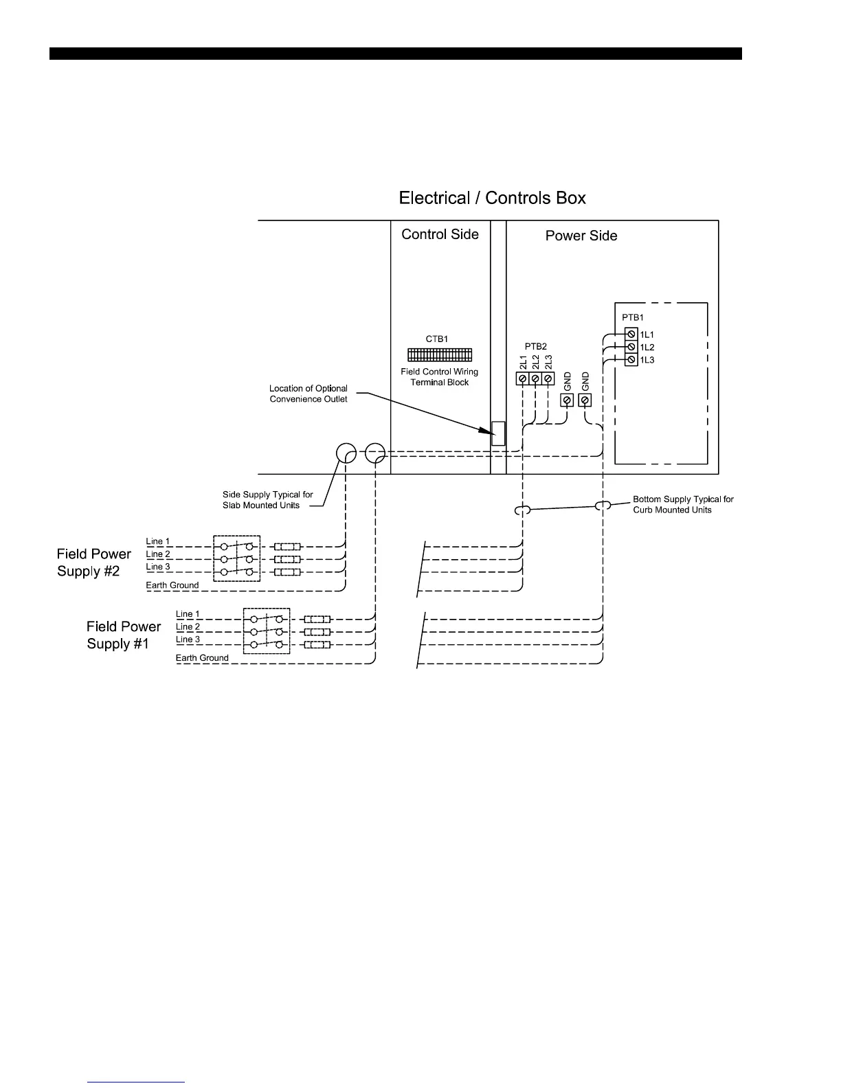
UNIT POWER SUPPLY WIRING,
OPTIONAL DUAL POINT
FIGURE 7 - DUAL POINT POWER SUPPLY WIRING WITH NON-FUSED DISCONNECT
Power Wiring: TMAL120–150 (Cont'd)
NOTES:
1. All eld wiring must be provided through a eld-supplied fused disconnect switch to the unit terminals (or optional molded disconnect
switch).
2. All electrical wiring must be made in accordance with all N.E.C. and/or local code requirements.
3. Consult the IOM manual (TPM3-NOM1) manual or unit nameplate data to determine minimum circuit ampacities (MCAs) and recom-
mended dual element fuse sizes.
4. MCA is based on U.L. Standard 1995, Section 36.14 (N.E.C. Section 440.34).
5. Maximum dual element fuse size is based on U.L. Standard 1995, Section 36.15 (N.E.C. Section 440.22)
6. Use copper conductors only.
7. On units with an optional disconnect switch, the supplied disconnect switch is a Disconnecting Means as dened in the N.E.C. Section
100, and is intended for isolating the unit from the available power supply to perform maintenance and troubleshooting. This disconnect
switch is not intended to be a load break device.