9
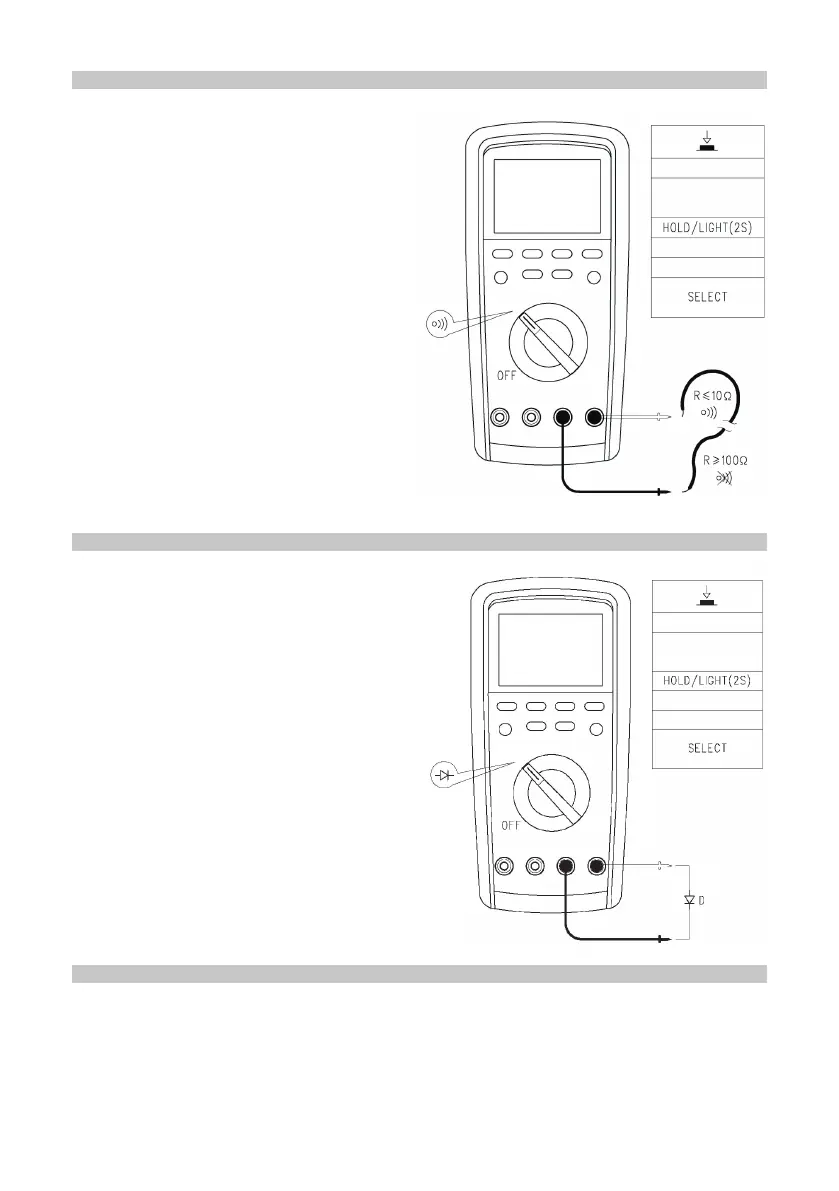
MEASURING CIRCUIT SWITCHING
• If resistance between two terminals
measured is higher than 100Ω, it shall
be deemed as open circuit and the
buzzer will not sound.
• If the resistance between the two
terminals measured is lower than
10Ω, it shall be deemed as sound
conductivity of a circuit and the buzzer
will produce a constant sound.
Caution
• While inspecting in-circuit circuit
switching, it is necessary to cut off the
power supply to the circuit under test
and discharge residual electric charge
in the capacitor before measuring.
• Do not input voltage higher than DC
30V or AC 30V to prevent personal
injury.
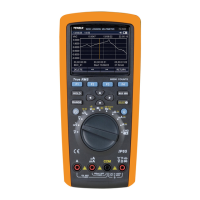
DIODE TEST
• The range of test voltage for diode is
about 0-3V.
• The auxiliary display shows “diod”.
Caution
• If the diode under test is in open circuit
or reverse polarity, it will display “OL”.
In terms of silicon PN junction, 500-
800mV shall be generally conrmed as
normal value.
• When measuring in-circuit mode, it is
necessary to cut off all the power to
the circuit under test and discharge
residual electric charge in the capacitor
before measuring.
• Do not input voltage higher than DC
30V or AC 30V in order to prevent
personal injury.
MEASURING CAPACITANCE
• When there is no input, the instrument will display a xed reading, which is the
inherent capacitance of the instrument.
• When measuring capacitance in small-range gear, the inherent value must be
deducted from the measured value to guarantee precise measurements.
• Therefore it is allowed to utilize the function of Relative Measuring of the