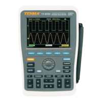
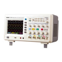
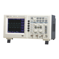
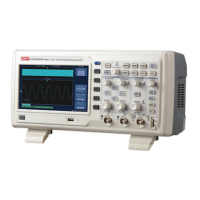
4
Power on the unit
• You can select from two power supply methods : internal battery power or external
DC adaptor power. Power supply voltage of the DC adaptor is grid voltage. After
connecting to power, start the self calibration process by pressing the [USER]
button then [F3]. This will ensure optimal performance.
Accessing signals
• Press UTILITY button then F1 and the screen will display DEFAULT SETUP.
• Connect the probe to the ChA input.
• Set the probe attenuation switch to 10X position.
Note You have to set the probe attenuation factor of the
oscilloscope. This factor changes the vertical range multiple to
ensure the measurement result correctly reects the amplitude of
the signal being tested.
Set the attenuation factor of the probe as follows: Select other
menu in Channel A then set probe ratio to 10X with the jog dial.
• Return
• K-return
• Normal
• Invert
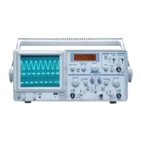
OPERATION
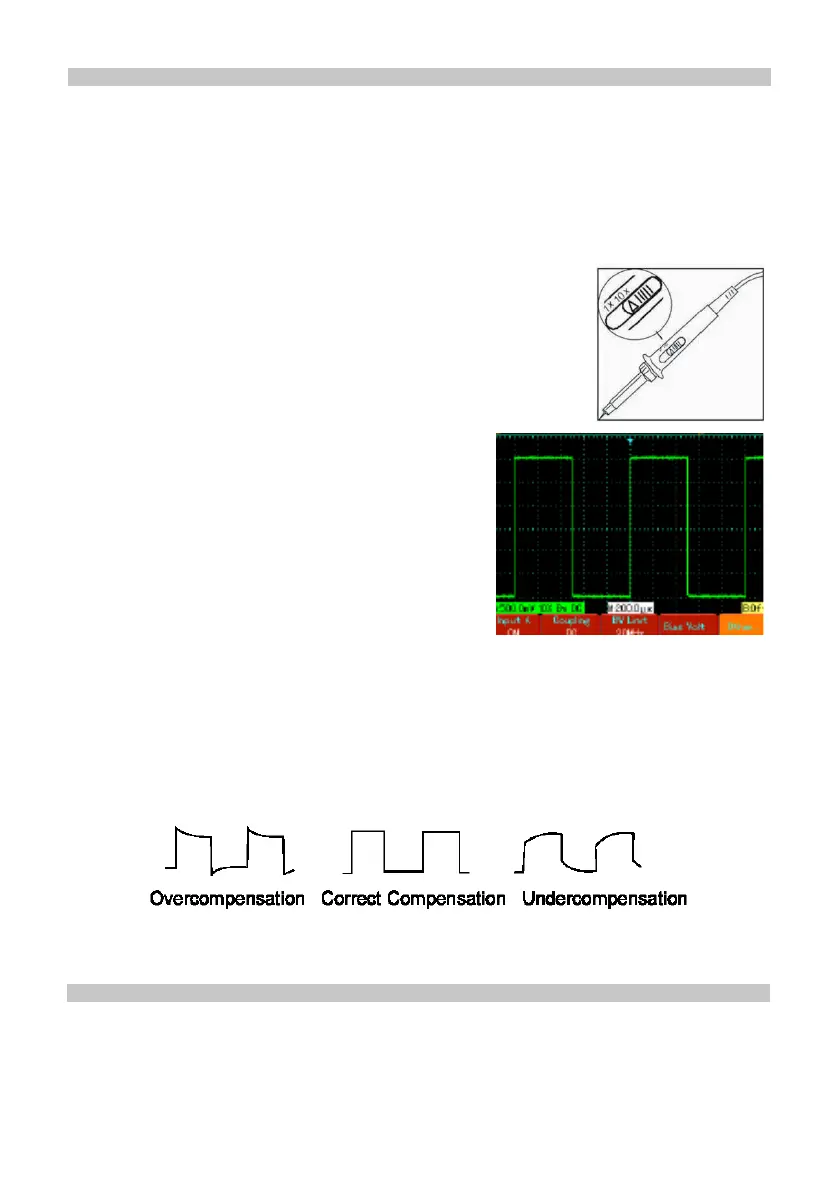
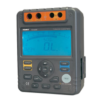
AUTOSET WAVEFORM DISPLAY
• Adjust the variable capacitor on the probe with an insulated screwdriver until a
correct waveform is achieved.
• The oscilloscope features an autoset function which automatically adjusts the
vertical deection factor, scanning time base and trigger mode based on the input
signal until the most appropriate waveform is displayed.
• This function only operates when the signal to be measured is 50Hz or above and
the duty ratio is larger than 1%.
• Connect the probe tip and ground clamp to the output terminal of the function signal
generator. Select a square wave of 1kHz output frequency and 3Vpp amplitude.
Press [AUTO] and you will see a 1kHZ/3Vpp square wave in the display in a few
seconds, as shown in Figure 1-5. Repeat steps 2 and 3 to check Channel B.
• Input A : On
Coupling : DC
Bandwidth limit ; Full bandwidth
Bias Voltage : Others