8
Setting bias voltage
• Bias voltage is suitable for observing the following signals:
• The input signal is made up of relatively high DC quantities and relatively low AC
quantities.
• The input AC signal is very low in frequency and contains DC quantities. AC mode
is unsuitable.
• Duty ratio of the signal is too small. Waveform details are hard to observe even in
AC mode.
Setting the probe rate
• To match the probe attenuation factor setup, it is
necessary to set up the probe attenuation factor
in the channel operation menu accordingly. For
example, when the probe attenuation factor is 10:1,
set the probe attenuation factor at 10X in the menu.
• Apply this principle to other values to ensure the
voltage reading is correct.
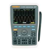
• Press [A] to turn Channel A on, then press [F5].
Select “Others” and select 10X probe ratio with the
jog dial, as shown.
• Next press the jog dial once to conrm, then press
the jog dial again to close the menu.
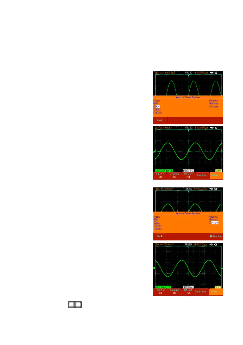
The screen shows the setup and vertical range
display when the probe is set at 10:1.
Setting the waveform polarity
• Inverted waveform : This indicates the signal is 180°
inverted in relation to the channel ground level. The
example below shows the setup for signal inversion
and the display for inverted signal.
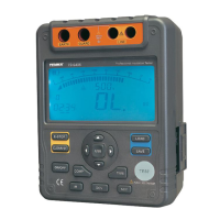
• Press [A] to turn Channel A on.
• Press [F5]. Select “Others” and select inverted
polarity, as shown in Figure 2-13.
• Press the jog dial once to conrm, then press the jog
dial again to close the menu.
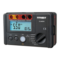
• The screen shows the channel polarity inverted.
Changing the signal time base and horizontal shift
• Accelerate or decelerate the oscilloscope’s scanning
rate by pressing
from 5ns/div~50s/div (72-9360).
Note: Minimum horizontal time base range of the 72-93xx Series varies from model to
model.
S nS