Do you have a question about the Tennant i-team i-mop xxl and is the answer not in the manual?
| Voltage | 24 V |
|---|---|
| Washed track | 64 cm |
| Vacuum | 5.8 kPa |
| Disc brush speed | 350 rpm |
| Disc brush pressure | 24.6 kg |
| Theoretical hourly yield | 2300 m2 |
| Estimated hourly yield | 1700 m2 |
| Solution tank capacity | 5L |
| Recovery tank capacity | 5L |
| Number of disc brushes | 2 |
| Disc brush motor | 170 W (x2) |
| Vacuum motor | 180 W |
| Maximum floor slope for using the machine | 6% |
| No. of batteries | 2 |
| Built-in battery charger | No |
| Autonomy | 70 min |
| Construction standards | CE |
| Protection class | IP2X |
| Sound pressure level A in the operating position | 76 dB(A) |
| Sound power level A | 74 dB(A) |
| Width of machine passage | 64 cm |
|---|---|
| Machine weight empty (without batteries, with empty tanks) | 21 kg |
| Machine weight heavy (with batteries, with a full tank) | 35.3 kg |
Defines directional references used throughout the manual.
Safety warning about working near the machine without adequate fixed safety supports.
Safety precautions for transporting the machine via conveyance.
Explains hazard symbols (Danger, Warning, Caution, Notice, Consultation).
Provides essential safety warnings and operational guidelines.
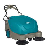
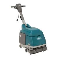
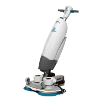
Lists detailed technical specifications of the i-mop machine.
Identifies and labels control panel components.
Visual identification and description of control panel elements.
Identifies and labels major external parts of the machine.
Identifies and labels internal components of the machine.
Outlines daily, monthly, and bi-annual maintenance tasks.
Step-by-step guide for replacing the brush motor.
Step-by-step guide for replacing the magnetic valve.
Step-by-step guide for assembling the mainboard.
Step-by-step guide for replacing the main lever.
Step-by-step guide for assembling the dashboard.
Instructions for replacing the Ø4 MM water channel brush tube.
Instructions for replacing the Ø6 MM transparent water channel tube.
Instructions for replacing the Ø6 MM water channel internal tube.
Step-by-step guide for replacing the vacuum motor.
Instructions for replacing the transport castor wheels.
Instructions for replacing the wheel support components.
Instructions for replacing filter cassette and transparent plastic deflector.
Step-by-step guide for cleaning the squeegee wheels.
How to adjust the water safe interval settings.
Provides the block diagram of the i-mop electrical system.
Detailed technical specifications for the i-mop batteries.
Detailed technical specifications for the i-mop charger.
A diagnostic guide for identifying and resolving machine issues.
Practical tips for diagnosing and fixing common problems.