75
PURGE AIR FROM THE BRAKE SYSTEM (2-wheel steer machines AGCO Axles)
NOTE :
This machine is equipped with hydraulic brakes which must be purged if any part of the brake system has
been disconnected. It is important that this procedure is used to make sure of satisfactory brake operation. The
brakes may be purged either manually or by using a pressurized venting kit. the procedure can only be completed
by two people.
Manual venting
1. Park the machine on flat level ground.
2. Fully dump the loader bucket and lower it to the
ground.
3. Lower the backhoe stabilizers and raise the rear
wheels clear of the ground.
4. Stop the engine.
5. Ensure the brakes are adjusted correctly (see
page 4).
6. Check the brake system fluid level (see page 4).
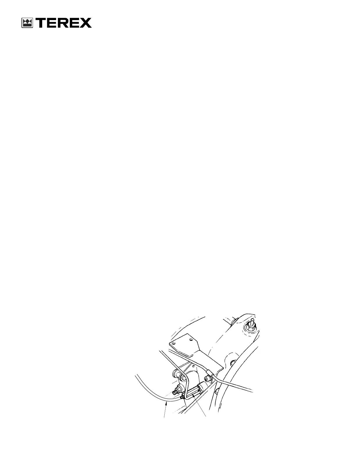
7. Fit clear plastic tubes (2) to the vent screws (1).
Position the other ends of the tubes (2) to drain
into suitable containers.
8. Open the left and the right vent screws (1).
9. Allow the brake fluid to drain into the containers
until an air-free flow of brake fluid is obtained.
NOTE :
This operation may be aided by pumping the
brake fluid by pressing and releasing the brake
pedals. Make sure the brake pedals remain latched
together and that the brake fluid in the reservoir
remains above the danger mark at all times.
10. Unlatch the brake pedals and close the left vent
screw (1).
11. Press and release the right brake pedal five
times.
12. Close the right vent screw (1) and open the left
vent screw (1).
13. Depress the left brake pedal 12 to 15 mm and
hold it in this position.
14. Press and release the right brake pedal five
times or until an air-free flow of brake fluid is
obtained from the left vent screw (1). Close the
left vent screw (1).
15. Operate the left and the right brake pedals. Make
sure the operation is firm and not ís “spongy”.
16. Only do steps 17 through 21 if the operation of
the pedals is not yet firm.
17. Press the left brake pedal.
18. Open the left vent screw (1) until the flow of
brake fluid stops.
19. Close the left vent screw (1) and release the left
brake pedal.
20. Do steps 17 through 19 until the left brake pedal
is firm.
21. Repeat steps 17 through 20 on the right vent
screw (1) and the right brake pedal.
22. Latch the left and the right brake pedals together.
23. Remove the plastic tubes (2) and the containers.
24. Check the brake system fluid level (see page 4).
789M297A
1
2