62
www.tescom-ups.gr
USER MANUAL
PRIME PLUS � 1/1 � 1-3 kVA � ΟNLINE UPS
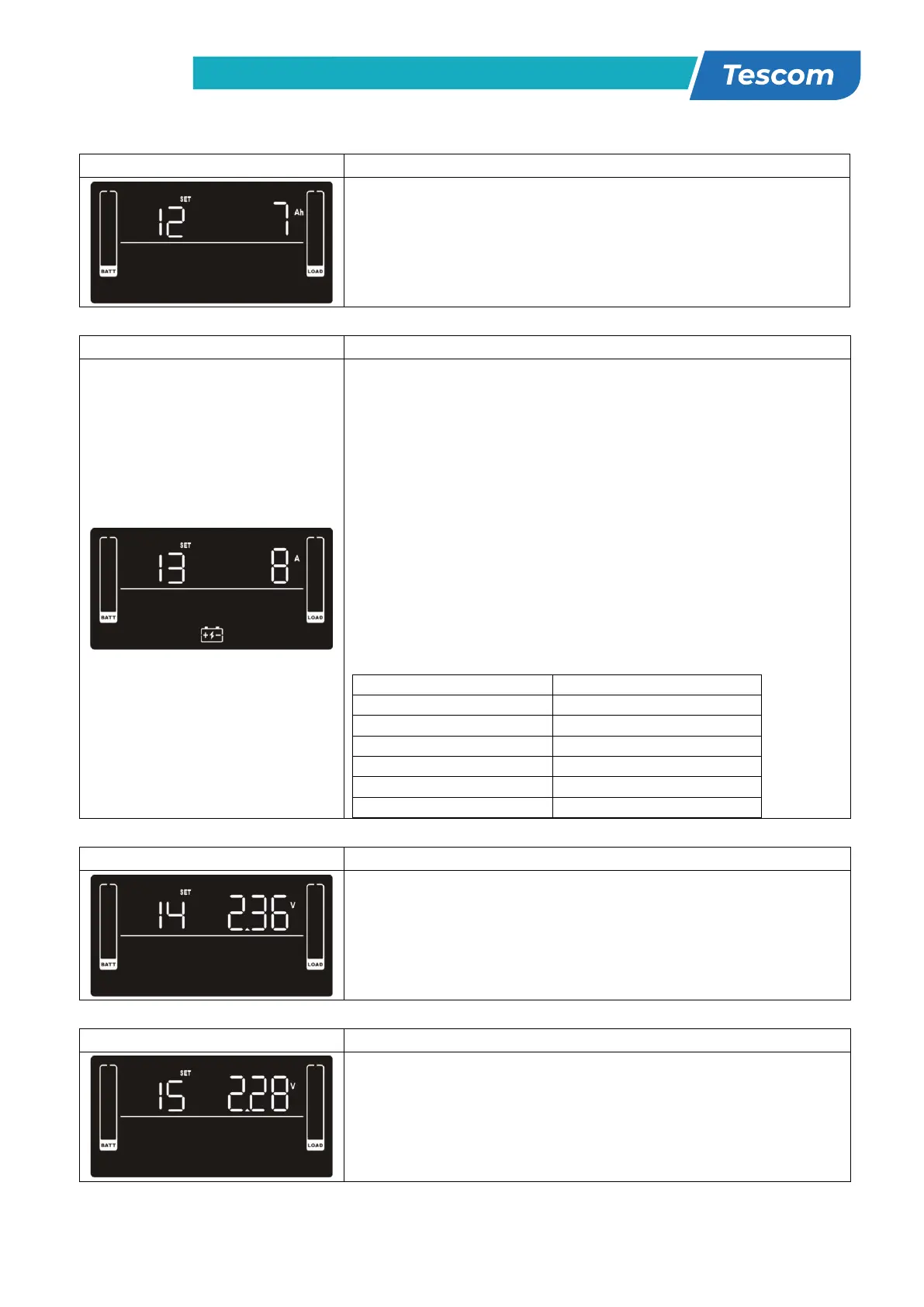
12: Battery total AH setting
Parameter 2: Set up the battery total AH of the UPS.
7-999: setting the battery total capacity from 7-999 in AH.
Please set the correct battery total capacity if external
battery bank is connected.
13: Maximum charger current setting
Parameter 2: Set up the charger maximum current.
For low voltage model with 24/36/48VDC
1/2/4/6/8: setting the charger maximum current
1/2/4/6/8 in Ampere. (Default: 2A)
For high voltage model with 24/36/48VDC
1/2/4/6/8/10/12: setting the charger maximum current
1/2/4/6/8/10/12 in Ampere. (Default: 2A)
For low voltage and high voltage model with 72/96VDC
1/2/4/6/8: setting the charger maximum current
1/2/4/6/8 in Ampere. (Default: 2A)
Note: Please set the appropriate charger current based on
battery capacity used. The recommended charging current
is 0.1C~0.3C of battery capacity as following table for
reference.
Total charging current (A)
14: Charger boost voltage setting
Parameter 2: Set up the charger boost voltage.
2.25-2.40: setting the charger boost voltage from 2.25
V/cell to 2.40V/cell. (Default: 2.36V/cell)
15: Charger float voltage setting
Parameter 2: Set up the charger float voltage.
2.20-2.33: setting the charger float voltage from 2.20
V/cell to 2.33V/cell. (Default: 2.28V/cell)
25
16: EPO logic setting
Parameter 2: Set up the EPO function control logic.
AO: Active Open (Default). When AO is selected as EPO
logic, it will activate EPO function with Pin 1 and Pin 2 in
open status.
AC: Active Close. When AC is selected as EPO logic, it will
activate EPO function with Pin 1 and Pin 2 in close status.
17: External output isolation transformer connection
Parameter 2: Allow or disallow external output isolation
transformer connection.
ENA: If selected, it’s allowed to connect to an external
output isolation transformer.
DIS: If selected, it’s not allowed to connect to external
output isolation transformer. (Default)
18: Display setting for autonomy time
Parameter 2: Set up the display setting for autonomy time
EAT: If EAT is selected, it will display the remaining
autonomy time. (Default)
RAT: If RAT is selected, it will show accumulated autonomy
time so far.
19: Acceptable input voltage range setting
Parameter 2: Set the acceptable high voltage point and
acceptable low voltage point for input voltage range by
pressing the Down key or Up key.
HLS: Input high voltage point
For 200/208/220/230/240 VAC models:
280/290/300: setting the high voltage point in parameter
2. (Default: 300Vac)
For 100/110/115/120/127 VAC models:
140/145/150: setting the high voltage point in parameter
2. (Default: 150Vac)
LLS: Bypass low voltage point
For 200/208/220/230/240 VAC models:
110/120/130/140/150/160: setting the low voltage
point in parameter 2. (Default: 110Vac)
For 100/110/115/120/127 VAC models:
55/60/65/70/75/80: setting the low voltage point in
parameter 2. (Default: 55Vac)
 Loading...